Speak To An Expert on 346-514-5073
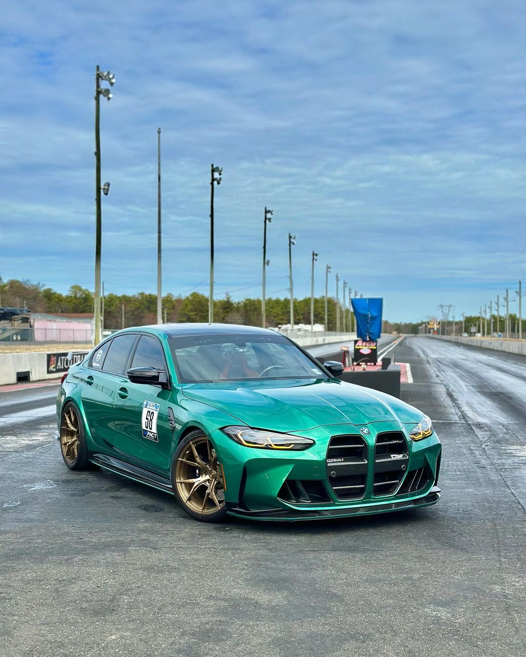
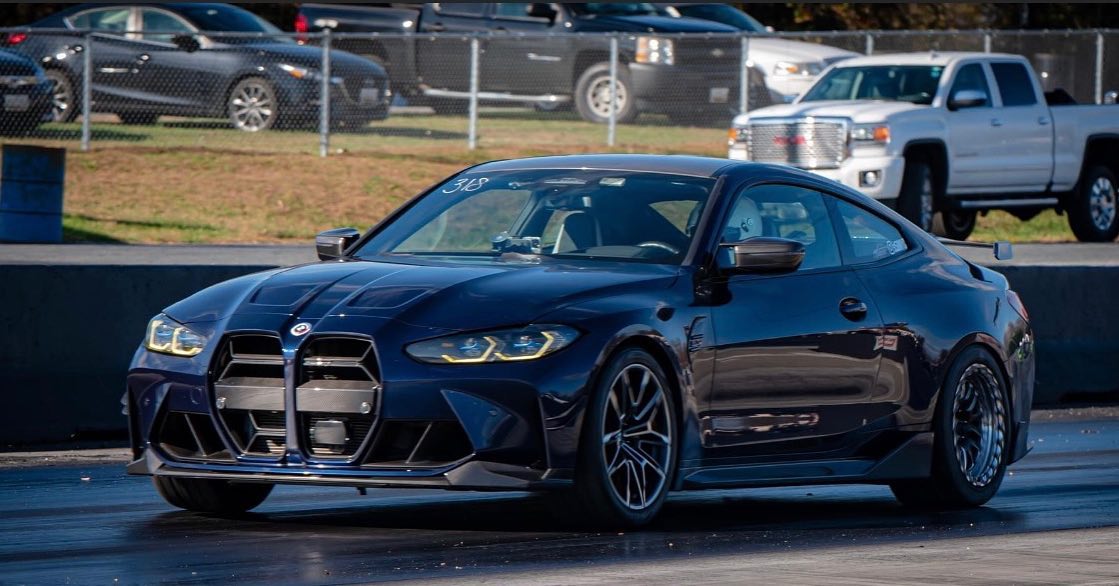
The BMW S58 engine found in the 2021+ G80 M3, G82 M4, F97 X3M, F98 X4M and upcoming G87 M2, is a powerhouse engine – it’s more than impressive. It takes everything from the previous industry darling, the B58 engine, and turns it up a notch. Combined with the option for all-wheel drive (xDrive), you’re arguably looking at the next “go-to” platform for big power in competitive motorsports for the next 5-10 years. Similar to what the Nissan GT-R became through the decade of the 2010’s. CSF again wanted to lead the way with this new BMW engine platform for cooling modifications. Particularly those needed to support power levels of 800+hp. Equally important was to future proof our 3-piece package for cars wanting to exceed 1200hp as the platform advances and matures. The center of it all is the CSF by PWR billet intake manifold with built in water-to-air charge-air-cooler.
We tapped into our unique and growing strategic partnership with PWR, who specializes in super-high performance, low volume motorsports cooling manufacturing. PWR supplies all the cooling for the F1 Grid, many teams in WRC, MotoGP, and NASCAR to name a few. They’ve become the perfect engineering and manufacturing partner for CSF over the past 3 years to help bring limited production items like this manifold to the performance aftermarket. All made in the USA, entirely built in-house with proper leak-testing procedures and product documentation on every single manifold before it ships.
Ask the competition if they undergo any of these procedures (more on this later)

Both CSF and PWR are certified, tier-1 OEM cooling system manufacturers. This is why it works… There is an immense level of respect between both companies as partners. Both acknowledge the successes of each other’s companies in our respective markets globally; PWR being the leader in competitive professional motorsports, military, aero space, and super high performance OEM cooling. CSF being a leader in the high-performance aftermarket, OEM, Agricultural, and Industrial segments. We both understand the nitty gritty nuances of heat transfer technology and manufacturing, all the way to the granular level of micron thicknesses in core specifications and how it all works. Not just with testing in our in-house wind-tunnels and computer simulations, but also validating in real-world racing and performance driving conditions.
So why is the CSF by PWR “Level-Up” BMW S58 Billet Intake-manifold better than anything else available on the market? Let’s break this down into the following main categories.
| OEM BMW Charge-Air-Cooler Specs | CSF Charge Air-Cooler-Specs | |
|---|---|---|
| Weight | 4.68 kg (10.32 lbs) | 7.42 kg (16.36 lbs) |
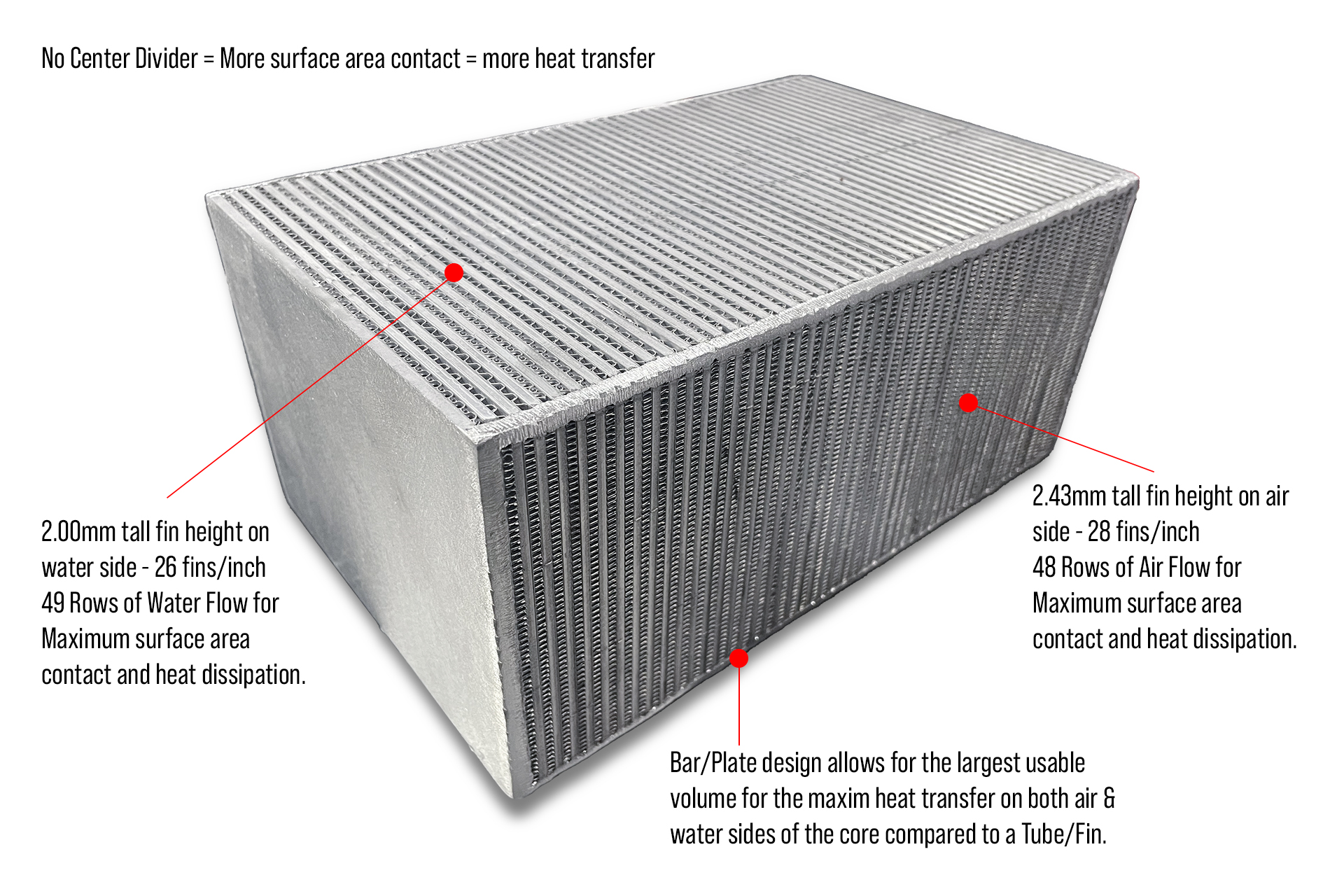
| Airside Fin height | 5.75 mm | 2.43 mm |
| Waterside Fin Height | 2.75 mm | 2.00 mm |
| Air Rows | 27 | 48 |
| Water Rows | 28 | 49 |
| Core Size | 142 mm x 230 mm x 99 mm 3233.34cc |
152mm x 239 mm x 110 mm 3996.08cc (23.6% more volume) |
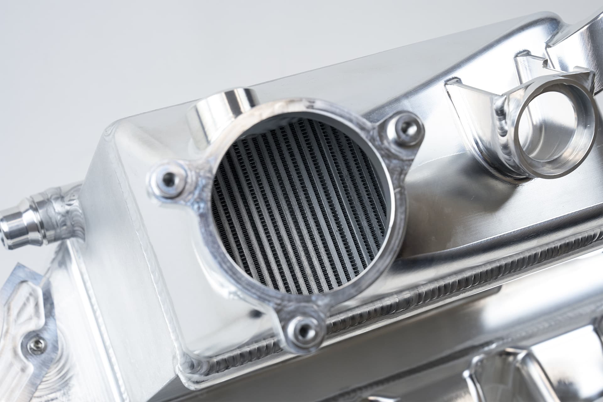
The CSF by PWR bar/plate intercooler core is far superior to not only the OEM extruded tube/fin core, but also without a doubt, will outperform any competitor in the performance aftermarket by a long shot. Let’s first discuss the competitive advantages of the CSF by PWR core, and then we’ll pick apart the competition using their own published information.
PWR manufactures this core in-house at its tier-1 OEM manufacturing facility in Indianapolis, USA. Each core is built by hand to aero-space level specifications and tolerances. What separates the core technology of PWR from the rest of the world is its ability to source and use extremely lightweight and thin materials in its cores. This allows for the absolute highest level of thermal transfer between the charge-air, and the water used as the medium to absorb the heat out of the charge air from the turbo. When combining the higher efficiency of the core design with an increase in core volume of ~25%, the result is the best-in-class cooling solution for the BMW S58 engine. This is not an opinion, it’s science and math. The logs in our testing section prove all of this.
Because of the delicate and thin material used in the manufacturing of these cores, they’re painstakingly slow to build. An experienced factory technician can build only about five of these a day. The cost of labor for the core building is the main factor for the high price of this manifold. A qualified technician who has the skill set to build these types of cores correctly, efficiently, and consistently is not cheap. Furthermore, because of the thinness of the materials used in these cores, it takes an exceptional and experienced welder to be able to weld these cores to the aluminum end tanks properly.
The temperature control and steadiness required by the welder to not blow through a cladding sheet that is only .3mm thick is on another level when it comes to being an experienced fabricator. Experienced Welders who can do this reliably are extremely expensive in the USA labor market. What you’re paying for is not just the actual product, but the labor and skill that is required to make such an exceptional product. I hope that my explanation on all of this really helps people understand why this product is so expensive.
Along with the performance benefits listed above, there are two main reasons why a bar/plate core was selected to be used for this application:
When it comes to achieving the best thermal transfer efficiency in a charge-air-cooler, the preferred method is a counter-flow designed core: In the counter-flow arrangement, the water and air enter at opposite ends, flow in opposite directions, and leave at opposite ends.
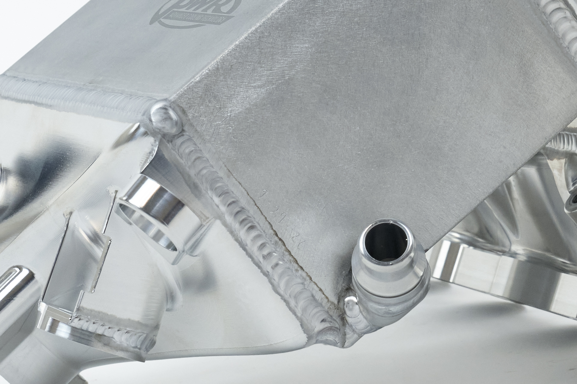
We don’t want to give all of our secrets away, but there is a tremendous amount of science and experience that has gone into the water-flow structure of the inlet & outlet “quick-connect” fittings and water inlet tube of the CSF manifold. The shape of the machined part increases the velocity of the water entering the core, and allows the water to travel in two different directions against the charge air that is entering from the throttle body.
Normally I would never do this. It’s not my style to call out any competitors on false claims used in their marketing. I typically don’t respond to negativity thrown our way. All it does is just shed light on clout-chaser companies that we compete against. However, the gloves have come off for this one.
I’m just going to call it as I see it – One of our competitors (We’ll refer to them as “Competitor R” from here) went to a “German” manufacturer, to have their core built for them. Unknowingly to them, they still don’t realize that this “German” manufacturer (We’ll refer to them as “Competitor W” from here) doesn’t make their own cores, but they’re sourced from a third party in China. I’ve been to the factory that makes cores for this manufacturer, and I’ve seen them being made with my own eyes. Regardless of this fact, Competitor R goes on to say (in their own marketing taken from their website – see below), that there is a reason, with a performance benefit, that they’ve adjusted to less efficiency than OEM specs. This is a flat out lie. Less rows on both the air and water side of the core, less surface area contact between the tubes/fins equals less performance and efficiency when comparing similar size cores.
Competitor W is purchasing the highest performance core spec their supplier has available, and re-selling it to Competitor R. There is a significant cost associated with new header plate tooling for a new core specification in a tube/fin configuration. Not to mention the cutters involved with a new fin height size which are upwards of $50,000 if done properly. “If” either Competitor W or Competitor R are getting any type of performance gain from their manifolds, it’s simply because of the increase in core volume compensating enough for the less efficient core they’ve decided to use.
I’ve marked some notes in red over the published data from Competitor R’s website. They’ve stated that they needed to increase the fin height because higher pressures create more restriction – that’s absolute nonsense from a technical perspective. The CSF by PWR core has 75% more channels that are less than half the height as the OEM, and the pressure drop data is better or equivalent to the OEM core throughout all of our testing. They say this because they’re trying to spin their inability of not being able to make a bespoke engineered core in-house.
This is what happens when you’re a small machine shop trying to make cooling products with limitations of not being a cooling expert, compared to two OEM supplier level companies filled with engineers specializing in thermal dynamics. If they really believed in the BS they’re trying to sell, then why for their B58 manifold are they using a bar/plate core instead? Simply sourcing whatever they can hands on, not the absolute best option like CSF is.
CSF has more experience in designing BMW Charge Air Coolers than any other aftermarket company. Between our coolers for the S55, S63, and B58 we have sold thousands of coolers. Each one of those products went through rigorous design, testing, and revisions during and sometimes after release. The CSF #8200 B58 “Super” Manifold is still a best seller and we’ve taken everything we learned from that manifold and applied it to the S58.
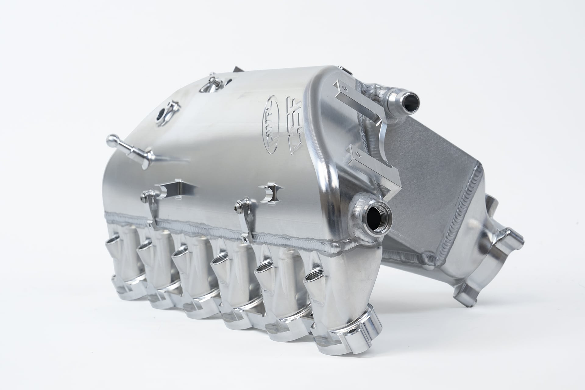
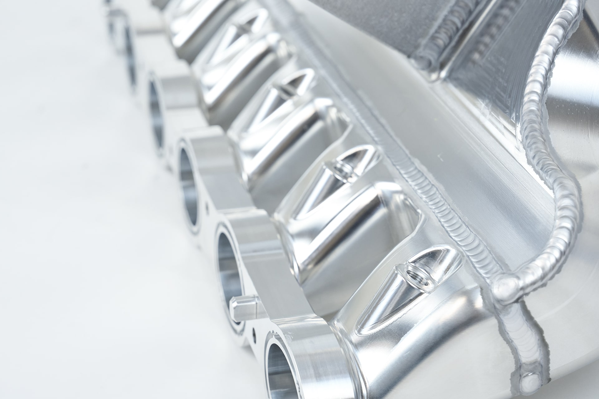
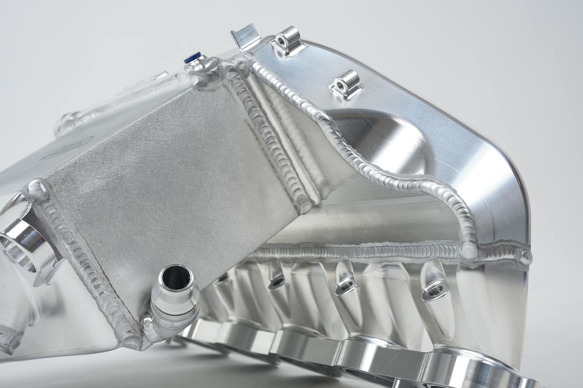
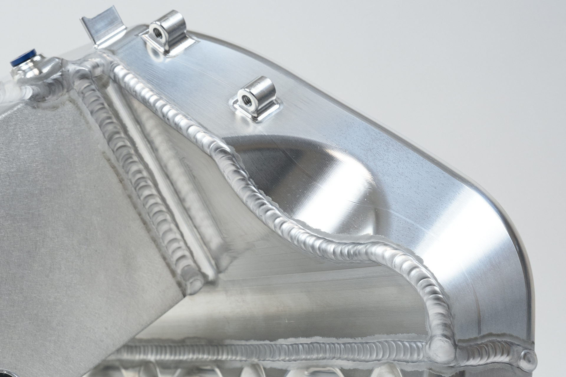
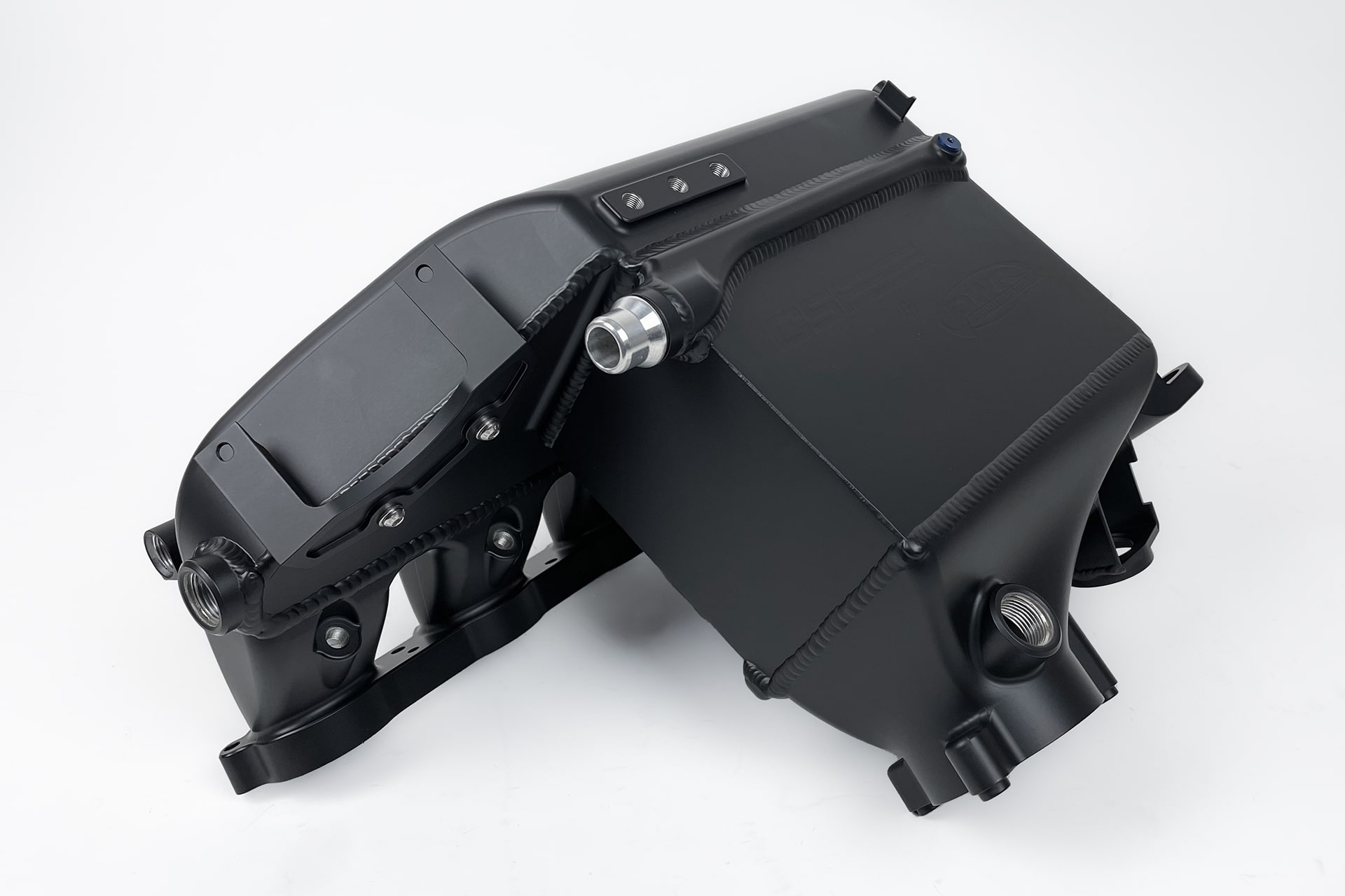
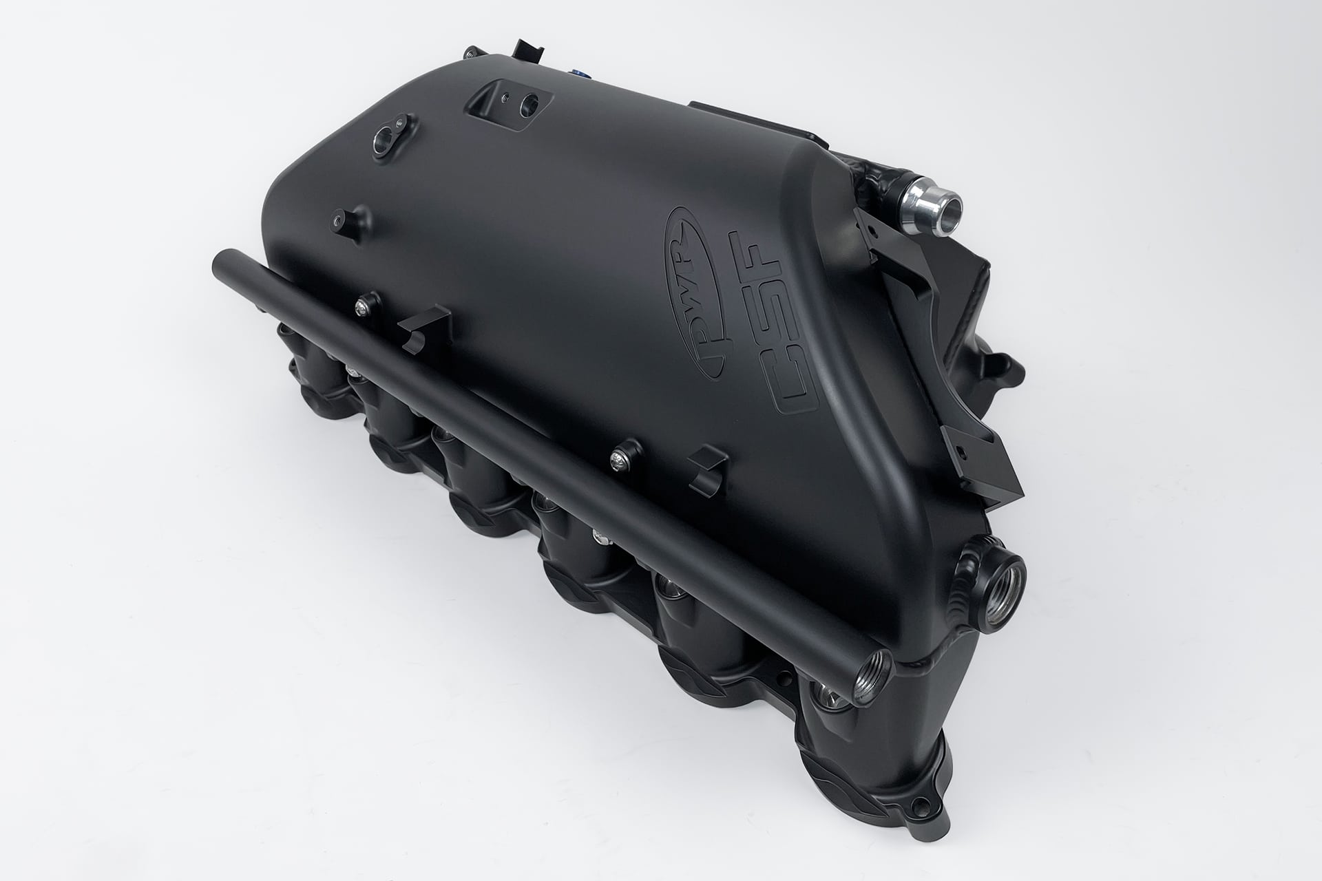
The CSF manifold is machined from the highest quality billet aluminum and TIG welded to form a solid one piece manifold. There are multiple benefits to this construction method.
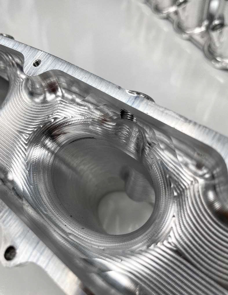
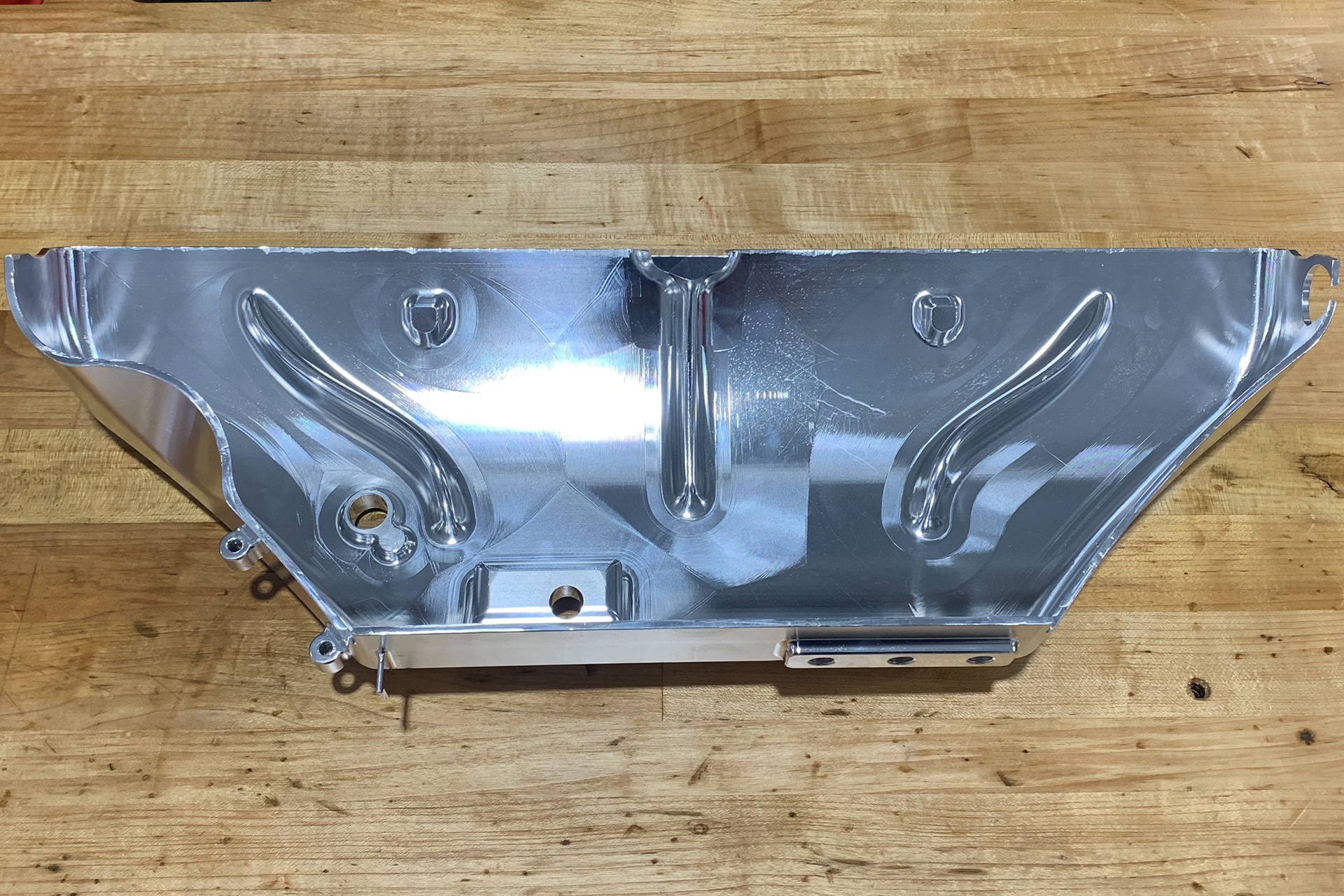
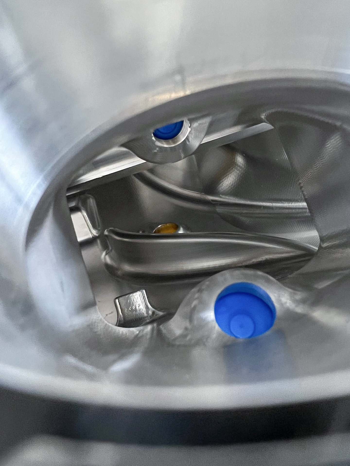
CSF has the largest plenum volume The joining of sections on any part can take up some space. Depending on the joining method, the required space will vary. In the case of the CSF Radiator, TIG Welding the billet aluminum sections together offers the strongest and most space efficient method. If you look inside the plenum and runners you can see the smooth transitions between each piece that maintains the smoothest airflow and the largest volume possible.
While looking at the factory plastic manifold, you can see the space taken up by the gasketed joins and strengthening lattice work. In the CSF Billet design, this wasted space is used to increase the plenum volume and optimize airflow. Competitor R’s manifold by contrast has a much smaller plenum volume despite being CNC Billet design.
Gaskets have their place in automotive engineering and construction. There is nothing inherently wrong with them as they are necessary for countless applications. However, in the case of manifold construction, they have their drawbacks. The required provisions for securing two pieces of a manifold with a gasket require additional space and materials. The extra material inside the plenum for bolts to secure two pieces of the manifold together reduces plenum volume.
Additionally, the gasket creates an extra weak point. For those running modest boost increases this may not be an issue, but CSF knows many BMW owners want to push for the most performance possible. This is why CSF elected the strongest construction possible to give our customers the strongest and most durable manifold possible.
Also, not all CNC machining is of the same quality. You can see the rougher cuts on the Competitor R Manifold within the plenum compared to CSF. The finer and smoother cuts offer smoother airflow but add to production costs. Every small detail like this was looked at when engineering the S58 Manifold to offer customers the best product possible.
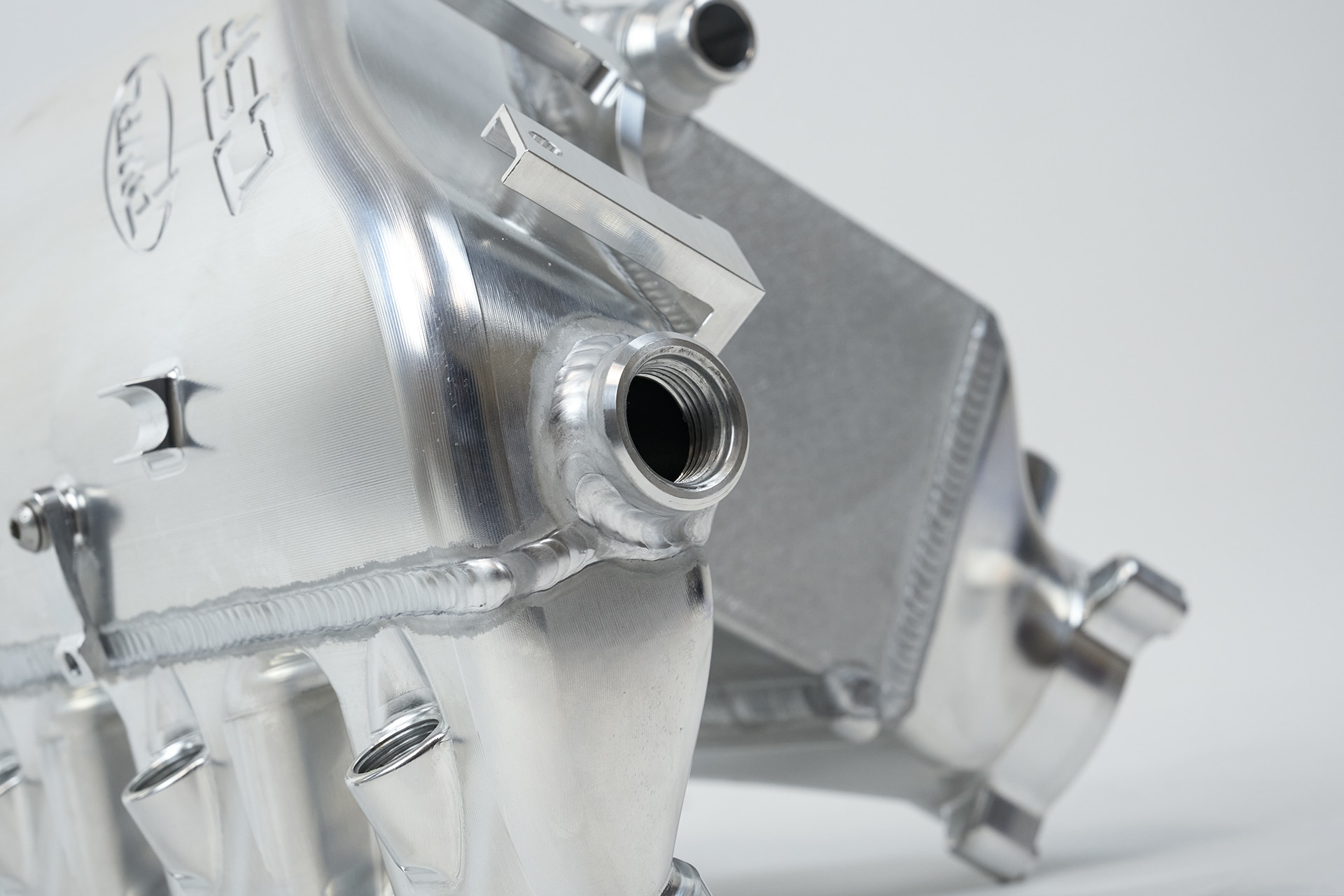
Water flow is just as important as air flow in an Air-To-Water system. Many companies will focus on the flow capabilities of their intercooler core, but forget to consider the flow in and out of the manifold. CSF spent extra time engineering and developing the water inlet and outlet channels for the intercooler core. The design ensures the most even flow of water through the cooler for optimal heat dissipation.
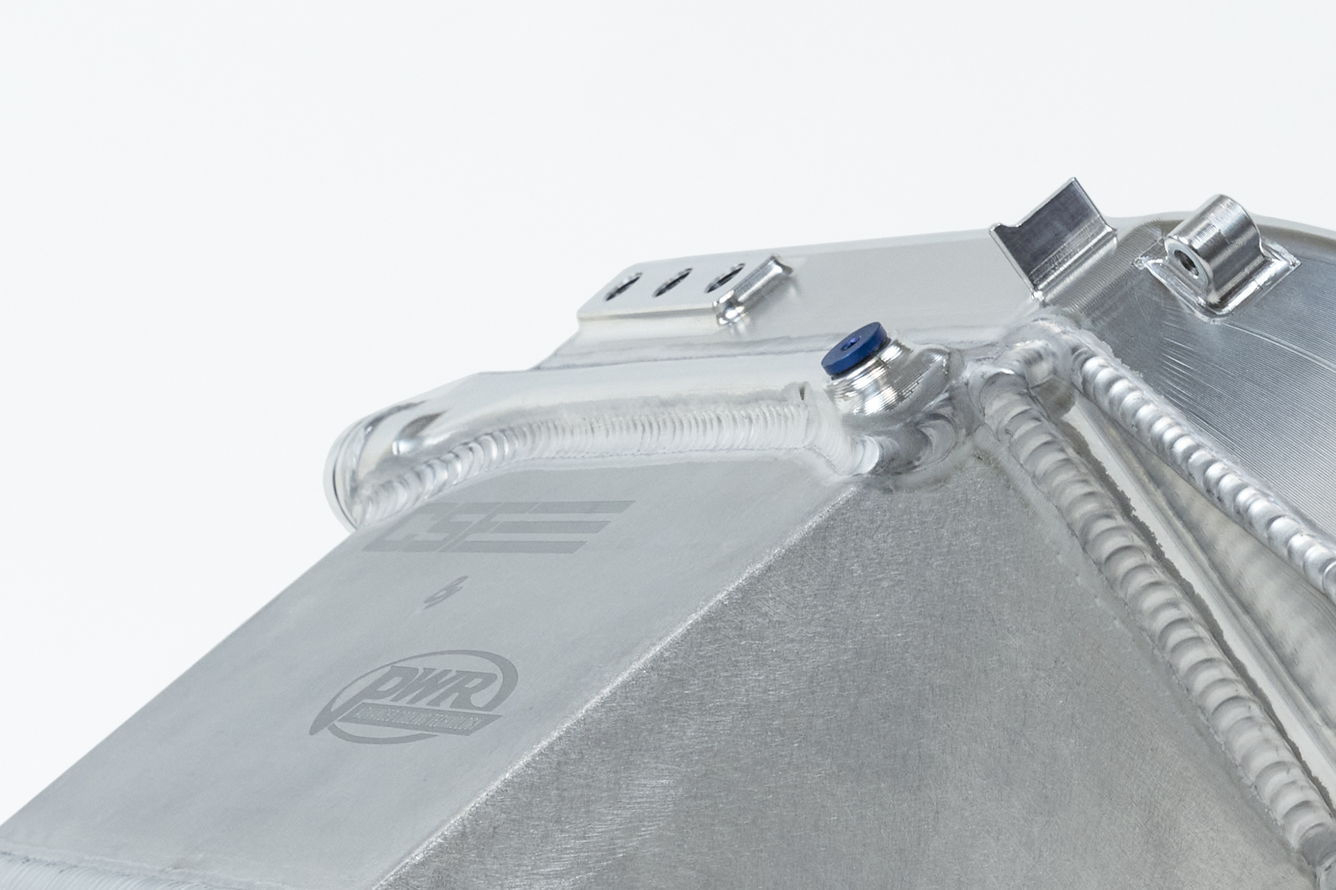
The water line quick connections on the core have enlarged inner diameters to improve flow. Reducing the restrictions here as much as possible returns the best possible flow for the air-to-water system. Better flow means the whole system can take advantage of not only the improved core, but also supporting systems like an upgraded heat exchanger (CSF #8215).
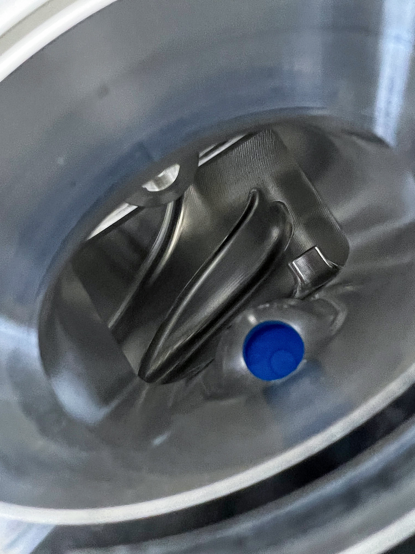
CSF also added a bleeder valve at the top of the charge air cooler to make the installation process a lot easier. Anyone who has installed a charge-air-cooler knows the frustration of getting all the air out. This bleeder value speeds up the process immensely and adds peace of mind that the system is properly bled before start up.
Proper airflow is essential for performance and reliability for any engine. This becomes even more important as you start tuning for a lot more power. If you have uneven air distribution between the plenum and runners you can have some cylinders not getting enough air and leading to potentially catastrophic failure. CSF and PWR used advanced CFD (Computational Fluid Dynamics) Software to engineer the airflow through the plenum. Special air guides were added to ensure each cylinder gets full airflow.
While the plenum can function fine without such air guides, CSF went the extra mile knowing customers will be pushing the S58 platform far past what BMW intended. The extra precaution is just one of many features that make the CSF “Level Up” Manifold stand out from the competition.
CSF Prides itself on designing and offering drop in fit cooling solutions that require no modifications to install. The CSF S58 “Level Up” Charge Air Cooler Manifold is no exception to that design philosophy. Special care was taken to ensure the simplest installation process possible with the finest attention to details.
No one likes having to leave factory harnesses and hoses unsecured after installing a new part. Every wire and wire have been accounted for with OEM+ style mounting provisions. Many of these details are exclusive to the CSF Manifold.
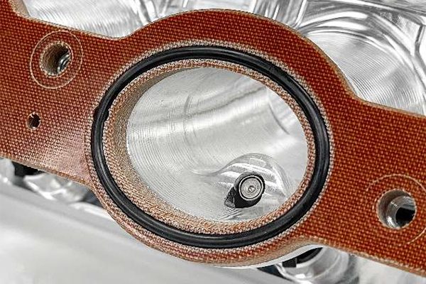
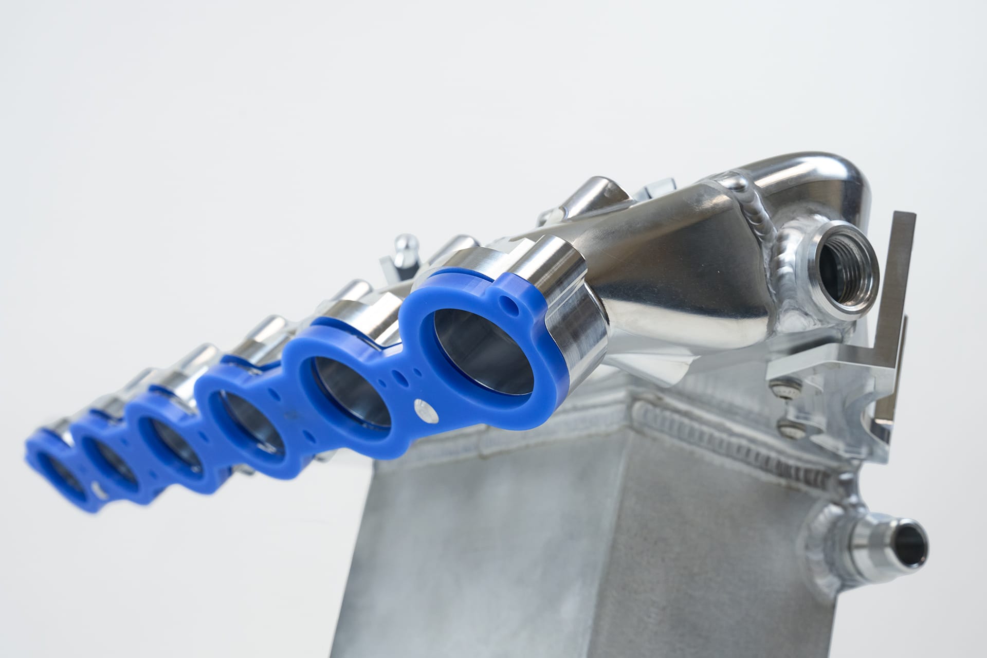
Each intake runner is machined for the OEM O-Rings with the factory style “teeth” to secure them (exclusive feature). This keeps the O-Rings from falling out during prep and installation. The Billet dowel pins between runners 1 and 2 as well as 5 and 6 both help secure the Thermal Rejection Competition Spacer. They also help keep the manifold aligned while bolting it into place. All in all, these features will make installation far less frustrating and were developed after test fit installs before final production.
Additionally, the Thermal Rejection Competition Spacer acts as a gasket between the cylinder head and the manifold. The precision machining and production of the spacer creates a perfect seal on top of the insulation properties. Competitor R’s Phenolic spacer does not meet the same standard forcing them to use aftermarket O-Rings in addition to the factory ones to create a positive seal between the manifold and cylinder head.
The CSF Manifold also features individual 1/8″ NPT ports on the underside of each intake runner. These ports can be used for Nitrous or Methanol injection. Not only is the location of the ports optimal for directly injecting your preferred go fast juice, but they are also hidden from plain view. This allows for a stealthy installation that is easy to conceal from unwanted attention.
Each port comes plugged with Steel 1/8″ NPT bungs for those who do not wish to run Nitrous or Methanol.
While designing and developing the S58 Manifold, CSF put in the extra legwork of securing a X3M/X4M Manifold. Since the G8X Platform and F9X X3M/X4M are both powered by the S58 but have different OEM part numbers for the manifold, it was important to understand the differences. There is an extra intake plenum connection on the front of the plenum. A threaded port was added with a block off -10 ORB bung or -10 ORB Quick Connect. This port can also be used for an optional blow off valve on G8X Platforms.
With the recent release of the G87 M2, CSF was able to confirm the OEM part number of the Charge Air Cooler Manifold. The new M2 uses the same OEM part number as the G8X M3/M4 and we already have one in transit for a first install.
A feature that was added to the B58 “Super” Manifold (CSF #8200) due to popular demand was a 3 Port Pad. This allowed customers to run extra sensors and provided additional vacuum sources. With such positive feedback for the feature CSF decided to include it from the start on the S58 Manifold. Located on the side of the plenum, it is easy to access and offers plenty of room for your chosen accessories.
There are two -10 ORB (O-Ring Boss) Fittings machined into the manifold. The lower is for crankcase ventilation and is standard use on all applications. ORB was chosen for its optimal sealing performance and the tolerances the fittings can produce. The Hard Anodized thin wall aluminum quick connect hose fittings offer the thinnest possible spec while being incredibly strong. This removes the potential restriction in air flow, an optimal seal, and the modularity to block off either fitting with included -10 ORB bungs.
Have you ever done an oil change and wondered why some jerk decided to make the oil filter impossible to get to? Well, you’re not alone. CSF wanted to avoid this type of frustration and included a special indent for easier oil filter access into the manifold. While this might seem like an obvious design feature to some, not all of our competitors are as thoughtful.
The designed protrusion above the recess was tested with CFD software to ensure smooth air delivery into the rear runners for the best possible airflow. The CSF Manifold is the only one to offer this feature and the only one that can run aftermarket oil filter caps.
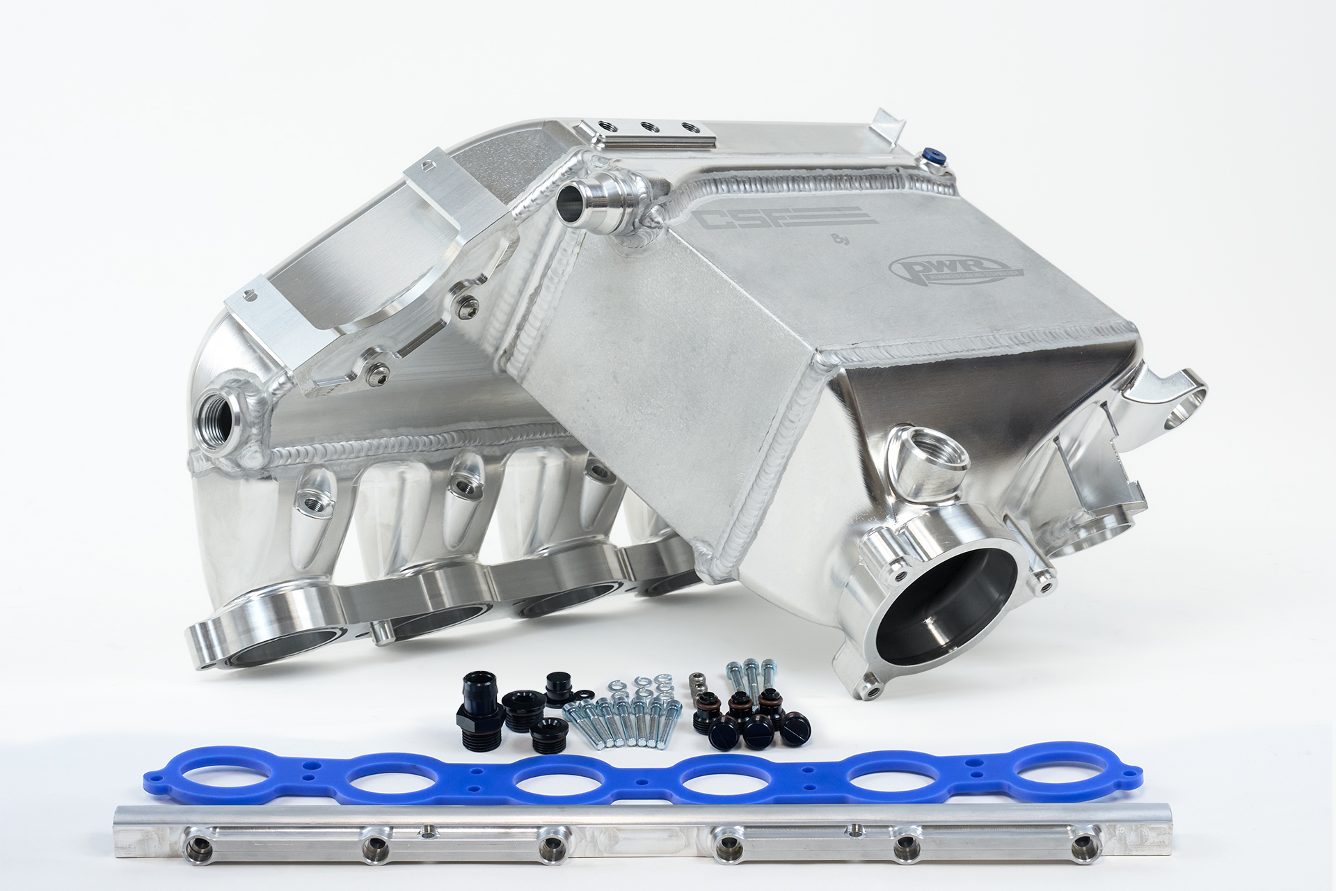
The CSF S58 “Level-Up” Charge-Air-Cooler Manifold comes with everything you need to install and setup. The only thing not included are injectors as most customers will select their preferred choice and required size based on their build. Injector information can be found here: Plug and Play Port Injection
There is also a complete instruction guide for both professional installers and ambitious DIYers. Like all CSF Products, this kit is a true “drop-in fit” installation.
Made from KIYLEX®, a patented revolutionary high-performance final stage polymer. KIYLEX® is as strong as aluminum and can withstand temperatures up to 1100°F. This spacer is designed to insulate the intake manifold from conductive heat transfer from the cylinder head.
This thermal barrier reduces manifold temperatures which helps lower Intake Air Temperatures (IATs), improve charge air cooler efficiency, and combats heat soak. CSF is the exclusive distributor for the KIYLEX® Intake Manifold Spacer for the S58 and B58 Motor.
The addition of the Thermal Rejection Spacer is especially useful for Drag/Roll-Racing Events where vehicles typically sit in staging lanes in-between racing. This causes extreme heat soak to the liquid-to-air manifold as there is not sufficient airflow passing over the front mount heat exchanger when the car is idling (which is responsible for cooling the charge air fluid that runs through the manifold). This causes the starting IATs on subsequent runs to be higher than on the initial run.
The Billet Aluminum and 100% TIG Welded construction offers incredible strength, which allows the manifold to withstand higher boost pressures compared to the OEM plastic manifold. However, aluminum has higher thermal conductivity than plastic resulting in a higher rate of heat transfer between the cylinder head and manifold. Thermal Rejection Spacer reduces heat transfer between the two metal components (cylinder head & manifold). The spacer absorbs the heat from the cylinder head and dissipates it rather than transferring it to the manifold.
The use of thermal barriers between manifolds and cylinder heads is nothing novel. Enthusiasts, Tuners, and Race teams have been using them for decades. The technology has come a long way over the years though and not everyone has caught up. Fiber impregnated phenolic resin is effective, however a bit cheap and crude compared to modern technology like KIYLEX®.
So what are Phenolics? Phenolics are resins that do NOT DISSIPATE HEAT but can only WITHSTAND HEAT. While blocking the heat transfer from the cylinder head will keep your manifold cooler, it will also make you cylinder hotter. Keeping that heat in the entire system is not wholly beneficial. Instead you are simply redirecting the issue of heat built up. CSF’s exclusive KIYLEX® spacer dissipates that extra heat lowering the temperature of the overall system and keeps your manifold from heat soaking.
KIYLEX is Self-Sealing, requires NO gaskets vs phenolic spacers which require additional O-Rings, Gaskets, or Sealant.
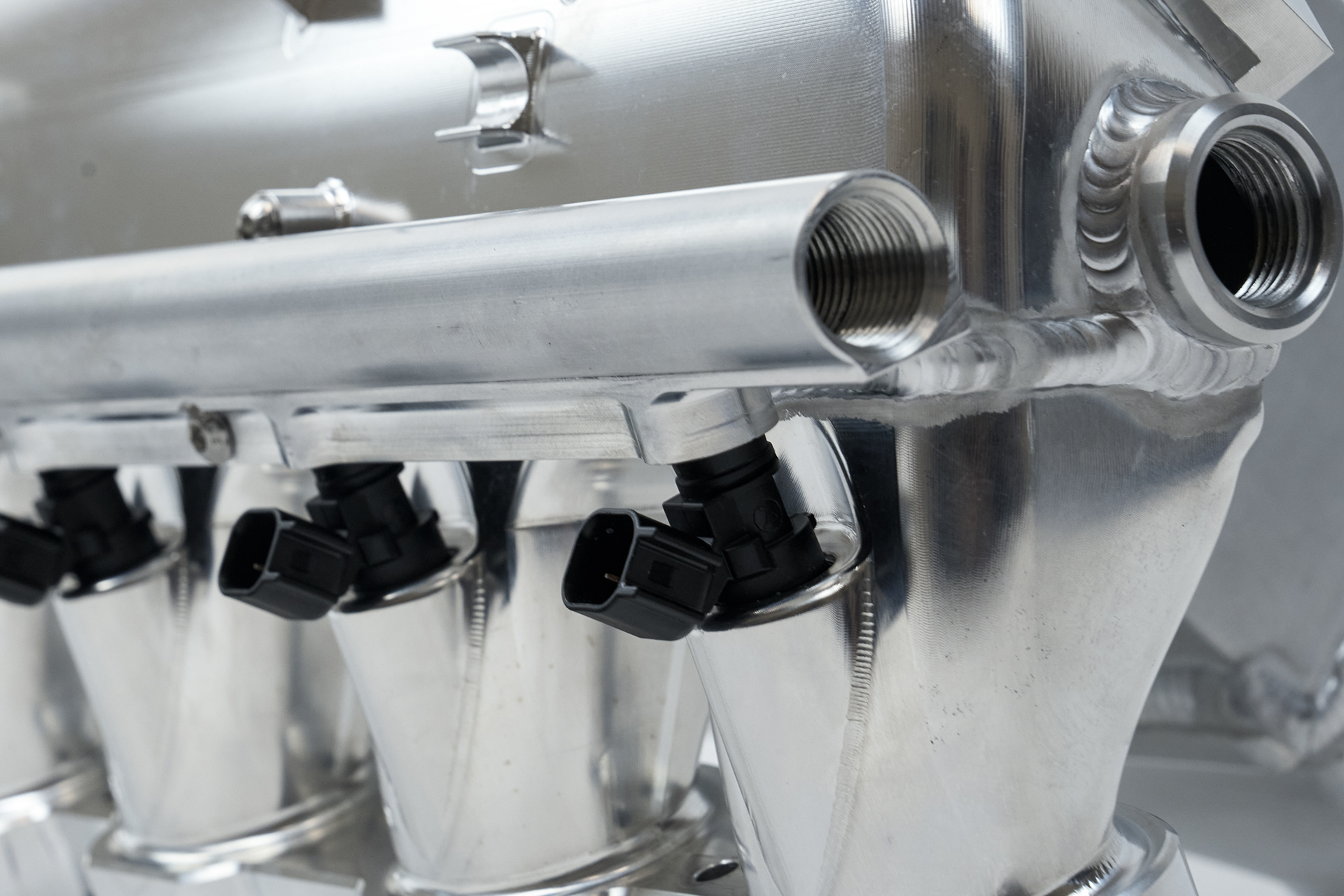
Every manifold includes an extruded fuel rail that has been machined to offer maximum flow for any applicable injector size. Whether you want to run standard pump gas, race gas, or E85, the fuel rail will work with your system. The AN-8 fuel rail comes with -8 internal hex plug fitting to use if running an OE style feed only fuel system but can be removed for a fuel system upgrade with fuel return.
One of the main reasons that CSF has partnered up with PWR and PWR North America is their ability to properly QC and leak test all of the CSF products they manufacture. As a fellow Tier-1 OEM Supplier with numerous ISO certifications, CSF is confident in the quality control procedures that PWR has implemented to make sure every single manifold that is approved for final packaging has undergone a strict and thorough check list of items to ensure only the absolute best parts are being shipped to CSF customers around the world.
Each core undergoes a light test as well as a visual inspection after being brazed in their in-house CAB (Controlled Atmosphere Brazing) oven. Each core then has the end plates, inlet water channel, and OEM Quick-Connects welded onto the unit. At this time, each unit is then pressure checked under water at 80 PSI for a continuous 5 minutes to ensure there are no leaks in the core. Our competitors are not cooling manufacturers, and although I’m sure they try their best to implement some type of leakage test, it’s definitely not at a production / factory level like PWR is able to achieve.
After welding on the air side tanks (Throttle body side for the inlet and plenum and runner for the outlet), the unit is then again pressure checked to again make sure there are no leaks from the welding process. Every threaded port on the manifold is checked by a single QC manager, every hole is checked for possible additional deburring, and all fine metal shavings are vacuumed and eliminated from the unit.
Furthermore every manifold is then inspected for any material handling defects which may have comprised the best-in class and flawless raw aluminum billet finish that we’re proud to offer as standard. The port injection kit, all installation hardware, and instructions are actually packaged and QC’d by CSF, then sent to PWR to have packaged along with the manifold during final assembly. Lastly the factory level production packaging using a high-level sealed air system ensures that the CSF by PWR S58 manifold will be delivered anywhere in the world without damage or defect.

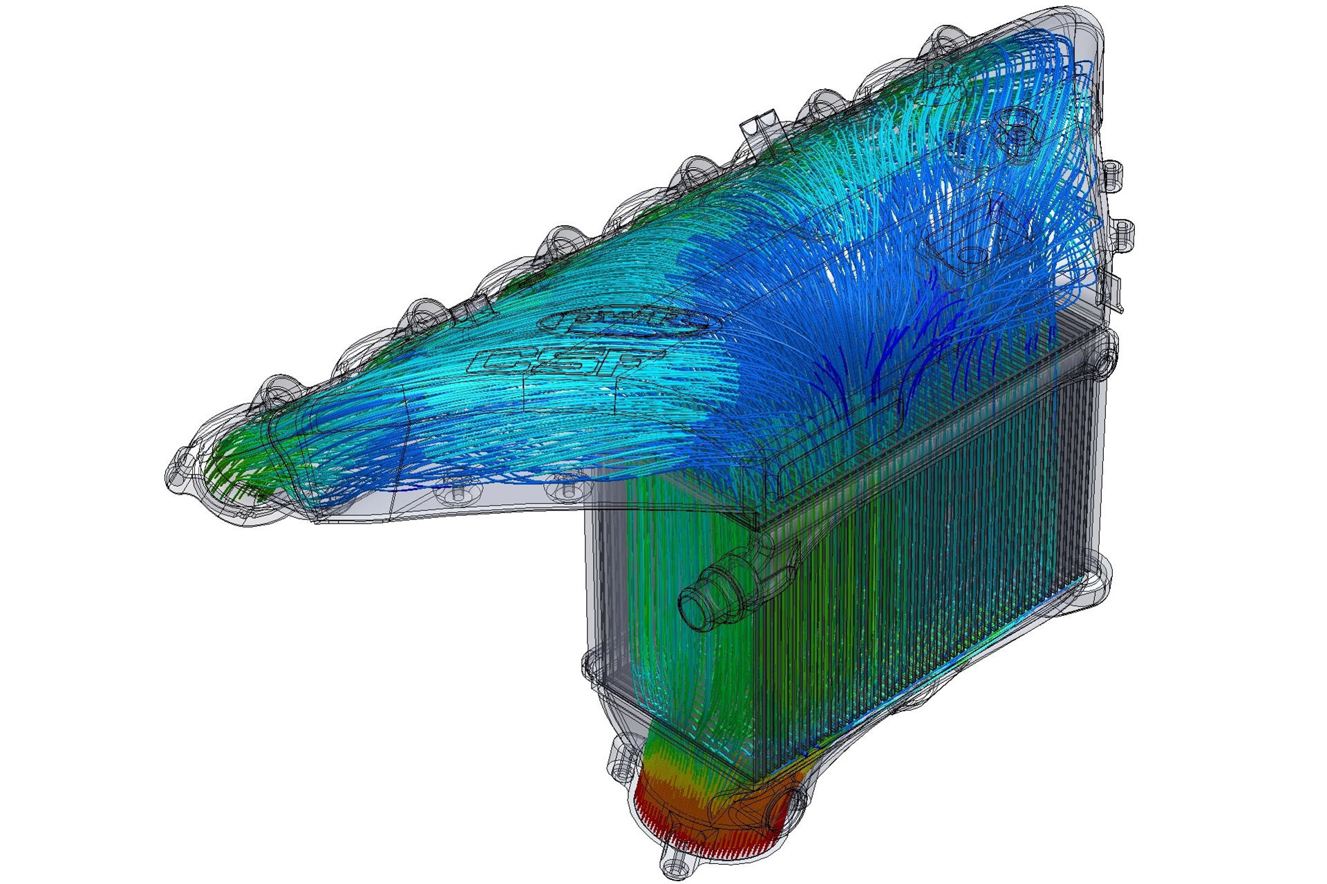
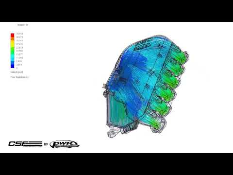
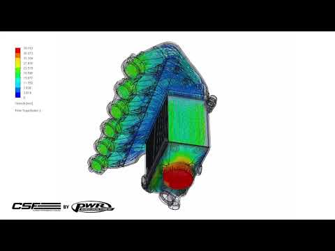
With over a year of development and testing there is a massive amount of CFD analysis that went into perfecting the S58 “Level Up” Manifold. While showing every iteration of testing CSF and PWR went through in the design phase, we are happy to show the results.
So what do all these colors and lines mean? For those who aren’t familiar with CFD (Computational Fluid Dynamics) simulations, it is exactly what it sounds like. The software simulates airflow through a design allowing for faster refinement and testing for a design before building it or making modifications. In the animations you can see a color key on the top left showing air velocity in meters/second. The animated lines show the path of air as it flows through the manifold.
You can see in Diagram 1 and in the animations how the air is evenly distributed through the core. As the air slows down while entering the plenum, the air guides help distribute the flow evenly into the runners. The result is a smooth and even distribution of air flow in both volume and velocity. Uneven distribution can lead to catastrophic failure in an engine so CSF and PWR work very hard to ensure your engine will be safe.
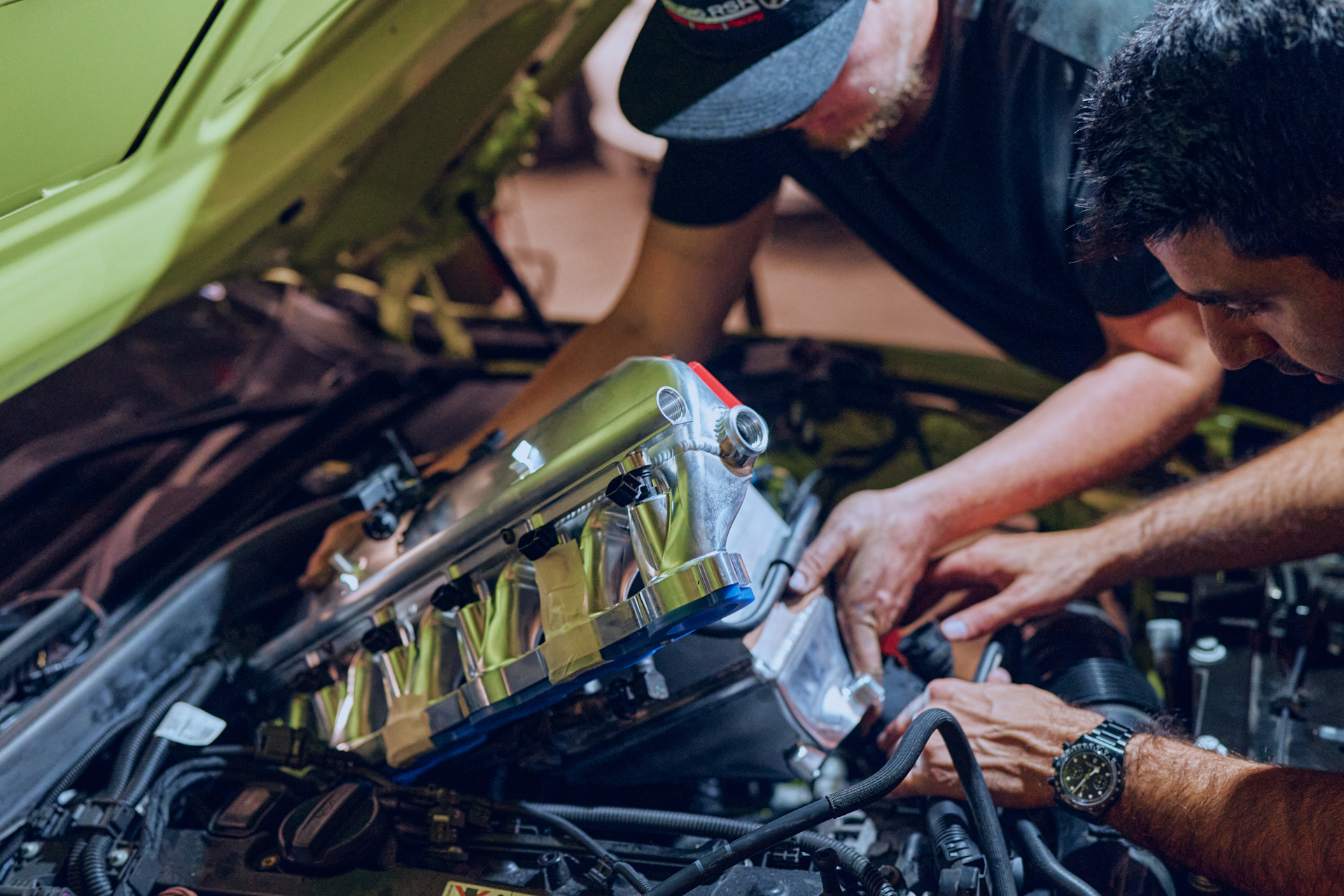
Dyno testing is crucial in the development process. While software can make the process of development much faster, there is no true substitute for real world testing. Upon initial release of the S58 “Level Up” Manifold, we had installed and tested our manifold on 3 different G8Xs. Initial testing showed impressive results and the cars all ran flawlessly. However, we wanted to test the limits of our manifold and see what it was really capable of.
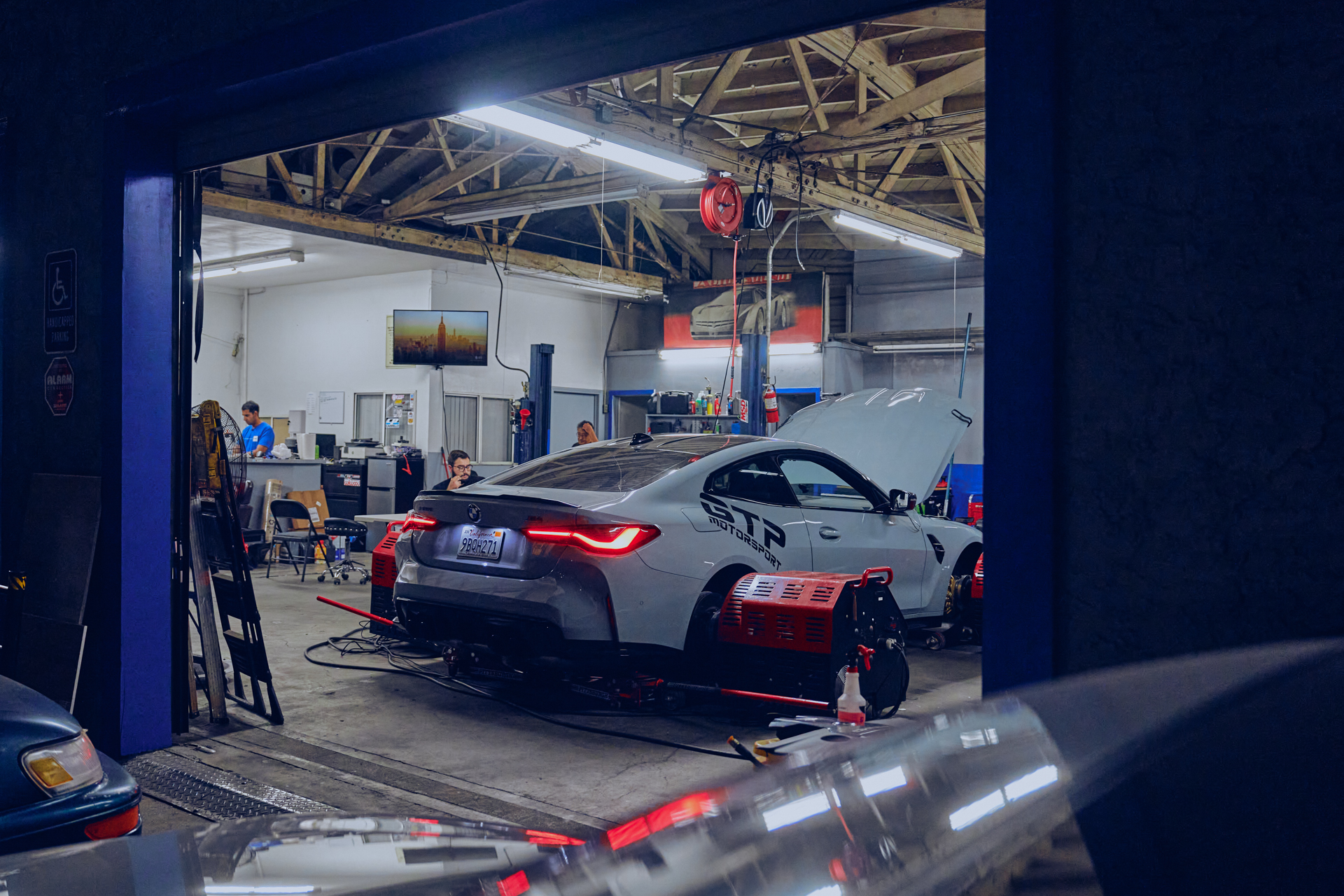
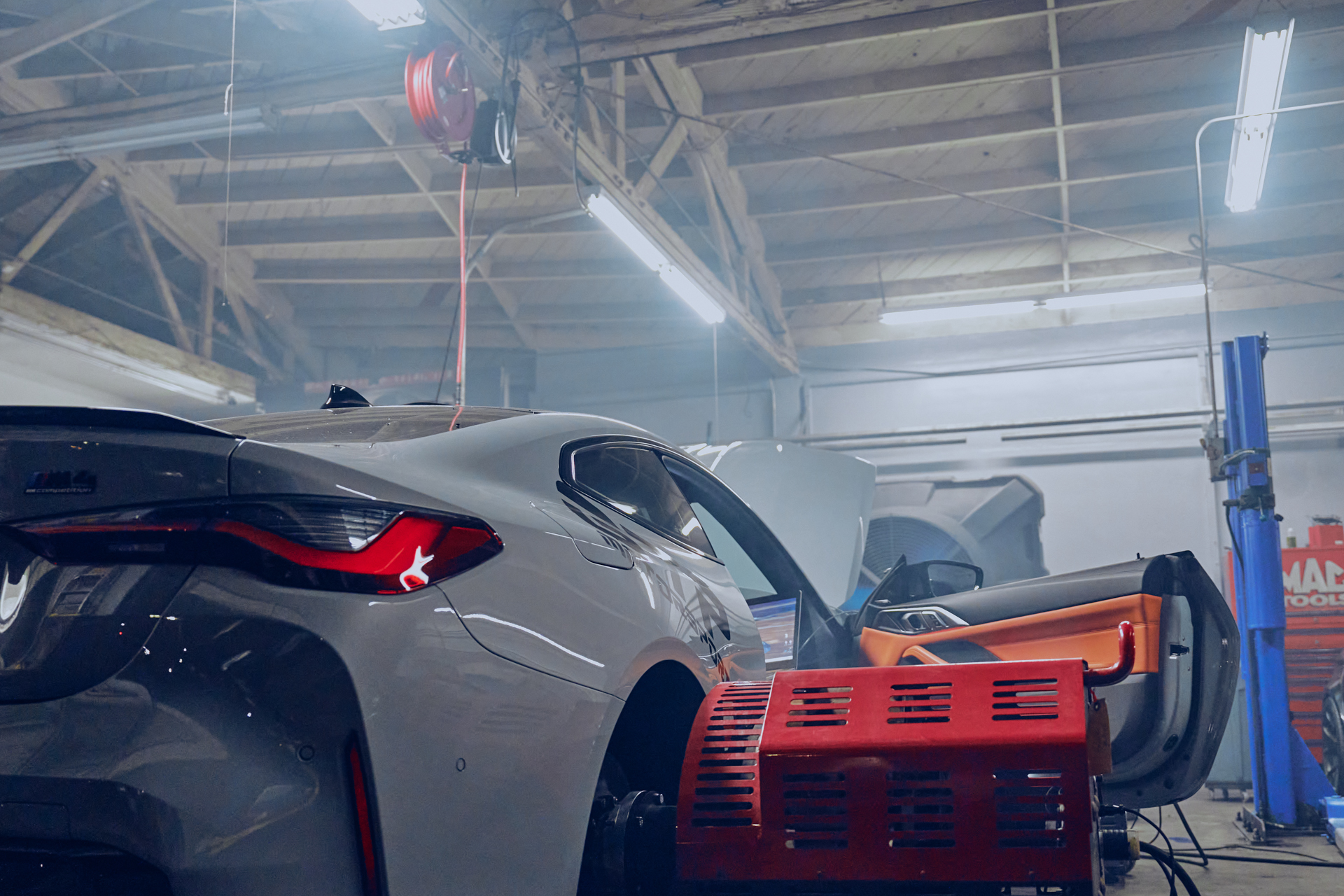
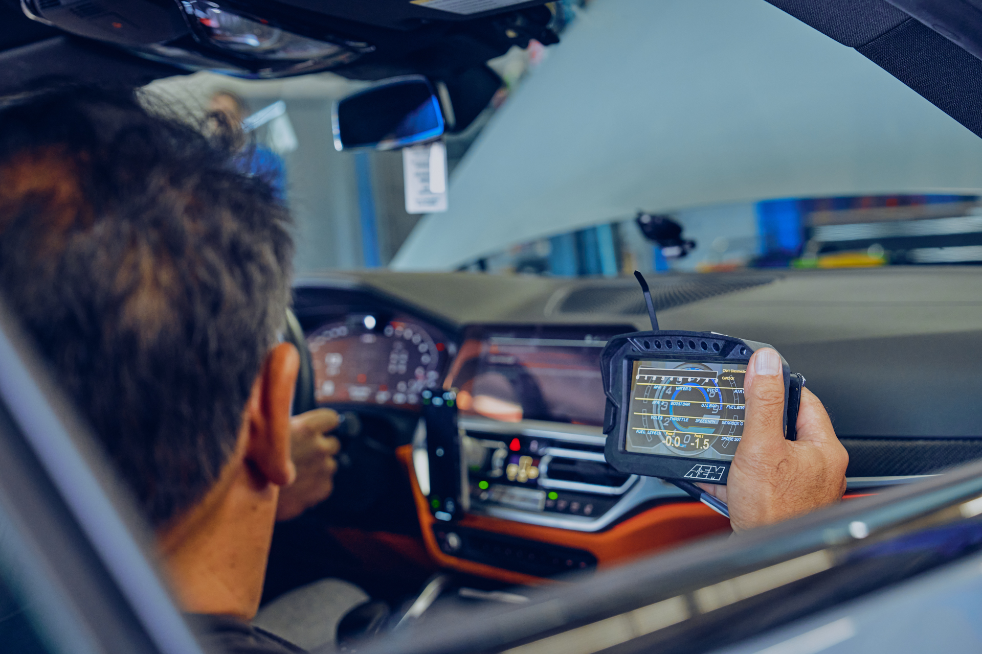
For more extreme testing, we headed over to GTP Motorsports Inc. in Hollywood, CA. Long time friends of CSF, Moto IQ was present for independent testing and validation of the results. GTP offered up their G82 M4 as a guinea pig and we got to work.

GTP G82 M4 Competition xDrive mod list:
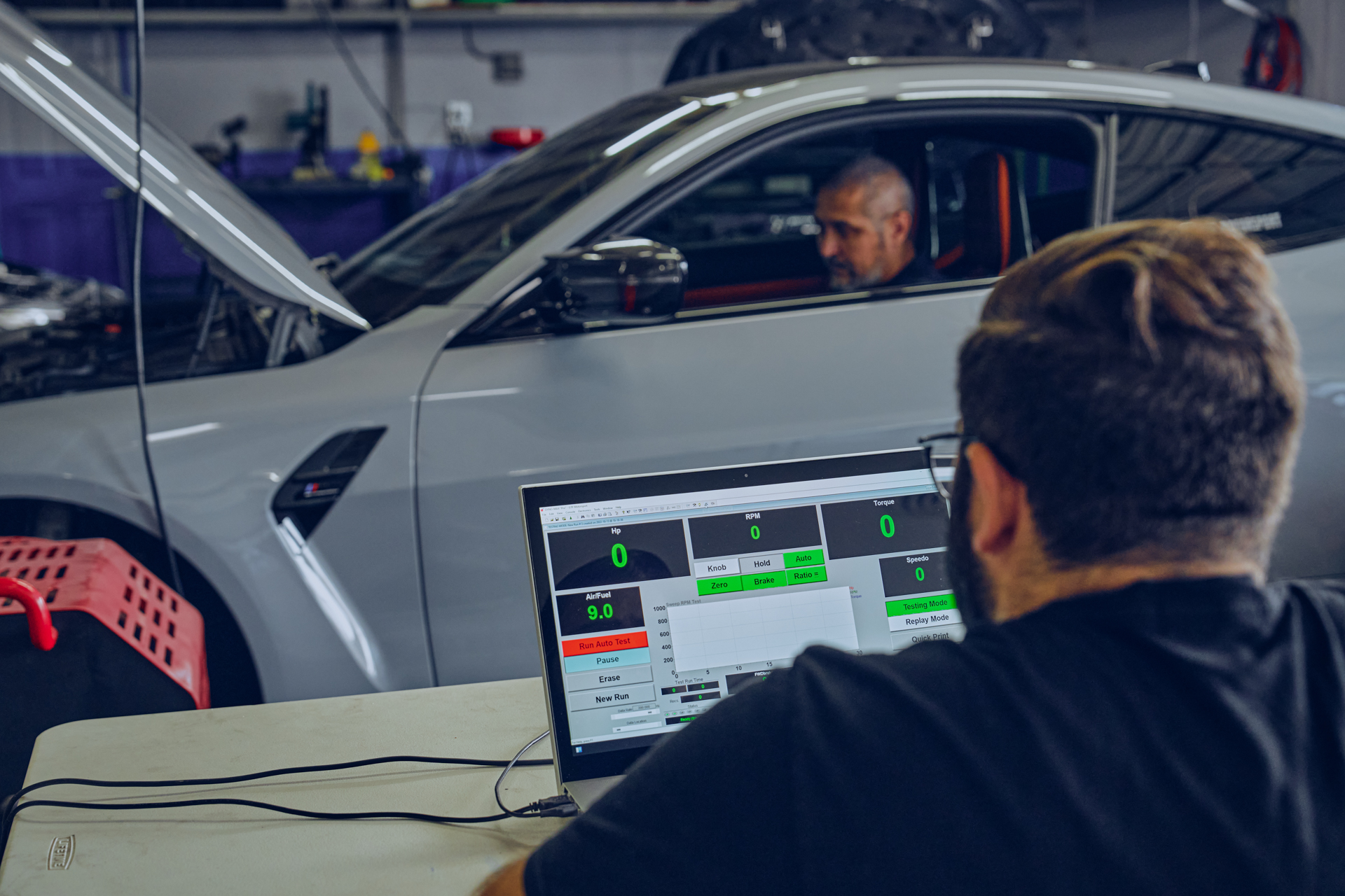
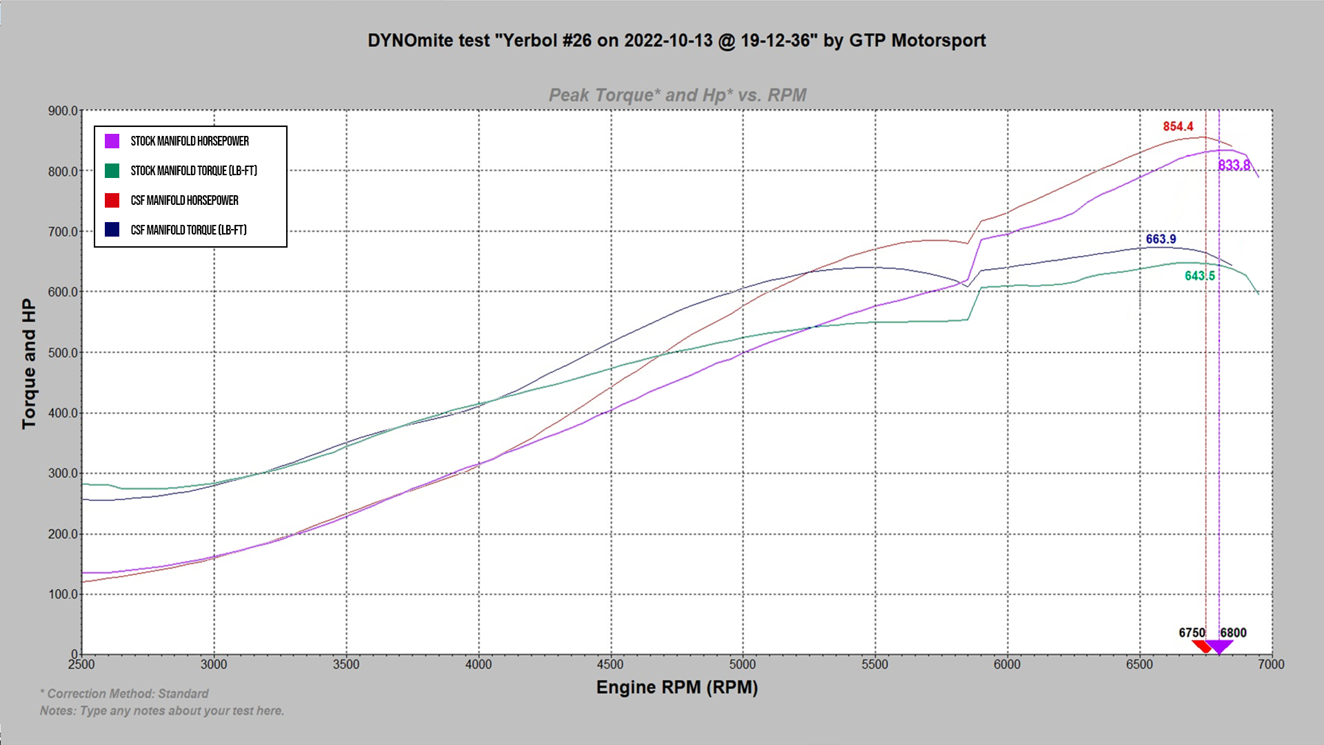
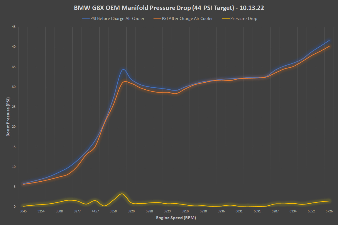
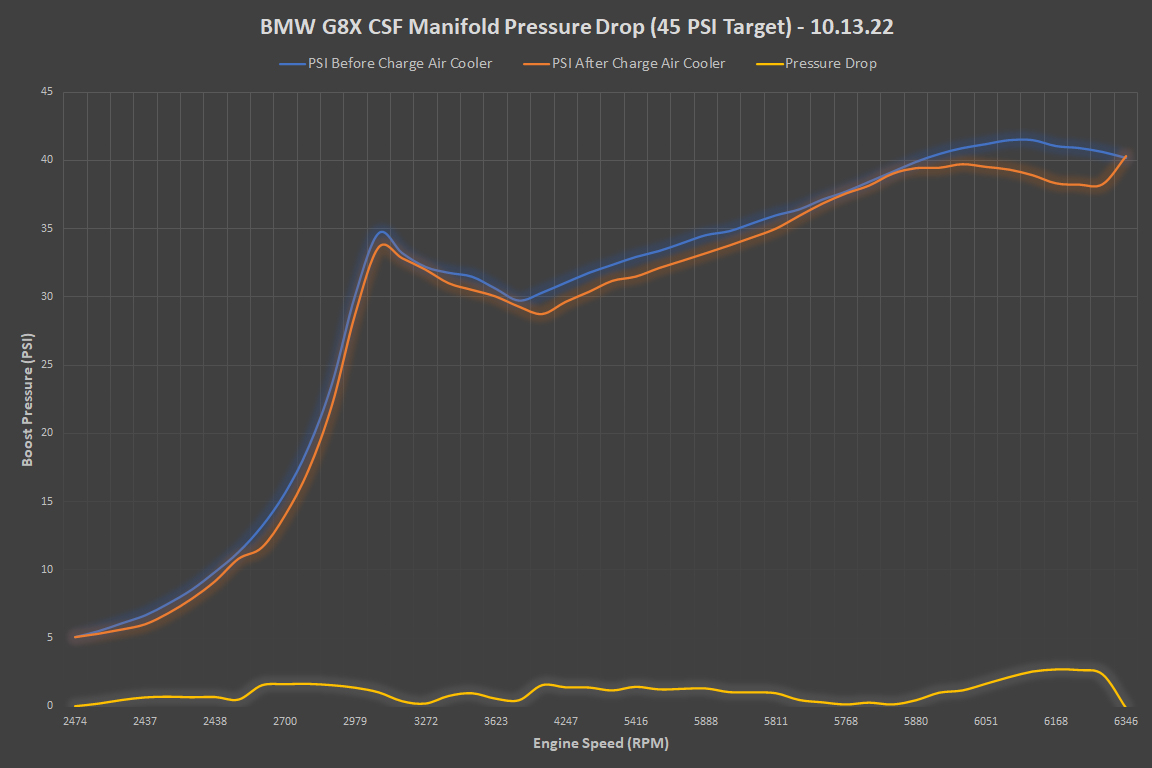
Testing was conducted on GTP’s Dynomite AWD2500 Dyno. Data was collected using an AEM CD-7. Baseline pulls were performed with the car tuned with 44 PSI as the target boost level. Actual boost level produced by the turbos in the OEM tests was 41.6 PSI. The post manifold installation pulls were performed with the car tuned with 45 PSI as the target boost level. Actual boost level produced by the turbos in the CSF tests was 41.5 PSI.
Note: we were very lucky the OEM Manifold lasted as long as it did. They have been known to fail at as low as 30 PSI. It did start leaking on some of the test runs but did not fail by some miracle.
When looking at the dyno test, you can see the overall improvement in the power curve from around 4500rpm all the way up to redline. If you are curious about the odd dip at around 5700rpm, the transmission was having issues with the power output and was slipping on every pull. While the pulls were done at different times of day and under different ambient temperatures, the results are using a standard correction. If you’d like to know about standard correction you can read about it on Dynomite’s website here: Corrected Horsepower
Heat soak resistance was tested on the dyno with 8 consecutive pulls from ~30 mph to ~130 mph. Each pull was full throttle with boost pressure set to 45 PSI. This test lasted 80 seconds and shows pulls 3 through 8.
Post cooler IATs started at 87.8°F (31°C) and increased by only 21.2°F (11.8°C) throughout the entire test. The test was supposed to go longer but the dyno began to smoke on the 8th pull so we deemed it prudent to stop. This kind of torture test is important to demonstrate the effectiveness of the heat exchanger under heavy load that customers might see in track driving.
Pressure drop is an important variable to measure when testing any type of intercooler. Measured pressure loss below 1-1.5 PSI is ideal. As stated earlier, PWR supplies all the cooling for the F1 Grid, many teams in WRC, MotoGP, NASCAR, and more. Every core design is Flow Bench tested, however they like most engineering companies know that this is merely a validation test and real world data will differ slightly. It is a great metric to have, but actual pressure will be slightly different as a flow bench cannot generate the exact conditions of a running engine.
The following flow charts were from data taken during the dyno pulls in the Horsepower & Torque section above.
| Metric | OEM Manifold | CSF Manifold |
|---|---|---|
| Pressure Drop at End of Run | 1.22 PSI | 1.10 PSI |
| Average Pressure Drop | 0.81 PSI | 1.05 PSI |
| Ambient Temp | 80°F (26.6°C) | 67°F (19.4°C) |
| HP | Torque | 833.8 WHP | 643.5 lb-ft | 854.4 WHP | 663.9 lb-ft |
| Time of Day | 3:18pm | 7:27pm |
Real world testing really shows how variable pressure drop and flow can truly behave. Overall, the CSF Manifold performed admirably.
We could easily throw out some big numbers and percentages without explaining what is really being shown by the data. The chart below shows the data from the same dyno pulls in the Horsepower & Torque section above.
| Metric | OEM Manifold | CSF Manifold | Deltas |
|---|---|---|---|
| Ambient temp | 80°F (26.7°C) | 67°F (19.4°C) | 13°F (7.2°C) |
| Pre-IC Temp Start | 172.4°F (78.0°C) | 134.4°F (56.9°C) | 38.0°F (21.1°C) |
| Post-IC Temp Start | 96.8°F (36.0°C) | 86.0°F (30.0°C) | 10.8°F (6.0°C) |
| Pre-IC Temp End | 394.2°F (201.2°C) | 348.8°F (176.0°C) | 45.4°F (25.2°C) |
| Post-IC Temp End | 112.2°F (44.6°C) | 93.2°F (34.0°C) | 19.0°F (10.6°C) |
| Average Delta Pre/Post IC IAT | 154.63°F (68.1°C) | 216.48°F (102.5°C) | -61.85°F (-34.4°C) |
| Average Efficiency | 86.60% | 89.06% | 2.46% |
| Maximum Efficiency | 90.14% | 92.20% | 2.06% |
Testing showed the average differential in CAT (Charge Air Temperature or Pre-IC Temp) to IAT (Post-IC Temp) for the CSF Manifold to be 61.85°F (34.4°C) lower than the OEM Manifold.
Intercooler efficiency is calculated with the following formula:
% Efficiency = (Pre-IC Temp – Post IC Temp)/(Pre-IC Temp – Ambient Temp)
Using this formula for the entire run, the overall average efficiency of the OEM Manifold was 86.60% (with a maximum efficiency of 90.14%). The overall average efficiency of the CSF Manifold was 89.06% (with a maximum efficiency of 92.20%). While an increase of efficiency 2.46% might not sound like a lot, everything should be taken in context.
It is generally accepted that the efficiency range of an air-to-water intercooler is ~75-95% with above 90% being very difficult to achieve. Improving on an intercooler that already has as much as a 90% efficiency rating is very difficult. Also, efficiency was not the singular goal when designing and building this manifold. The OEM manifold has been proven to commonly fail around 30-35 PSI of boost pressure. This obviously limits potential power you can make with this motor. We were lucky enough to have the OEM Manifold we were testing with hold up to several test runs at the targeted 44 PSI (Turbos could only produce 41.6 PSI). So in order to safely run more than 30-35 PSI consistently, you need a manifold that is strong enough to hold up to the pressure. The CSF by PWR Core is rated up to 120 PSI and the 100% TIG Welded Billet construction can handle far more pressure than that.
In summary, the Factory Charge-Air-Cooler is very efficient like everyone claims. However, CSF and PWR were able to engineer a much larger and stronger Charge-Air-Cooler capable of much higher horsepower and pressure while still improving efficiency.
One of the limitations to the initial tests were the Turbos and the Transmission. The turbos were maxing out at the target boost of 45 PSI and the Transmission was slipping. Just a few weeks later GTP was to tune and test the CSF Manifold on a F98 X4M with a built/stroked motor and larger turbos. This was a new world record for the S58 at the time (10/28/2022).
A couple months later, the X4M came back for some additional tuning and was the first S58 engine to break the 1000 WHP milestone.
With almost 100 CSF manifolds sold, we have seen more real world experience with our product than any of our competitors combined. From Drag Racing to Time Attack, Cooled by CSF S58 BMWs are breaking records and taking home trophies.
CSF is currently undergoing TÜV certification for installation and use in Germany, Belgium, and Switzerland. CSF is the only manufacturer, including German based Competitor W, who is investing the time and cost into this strict testing validation and approval. This further separates our CSF from our competitors and we expect to have full TÜV certification completed by May 2023
This has been the most heavily invested upon product that CSF has ever produced. The time spent in Research, Development, Testing, and Production has been monumental. However, we feel like it’s all been worth it. It’s about our pride in the BMW market and being the best. Based on the fact that we’ve sold 98 of these kits already before this official press release has been published, proves to us that the market already agrees. The confidence the BMW community has in CSF’s cooling products and our reputation has been humbling. With this official press release we really wanted to give every last detail of this manifold the attention it deserves. There are other choices out there, and I’m sure there will be more aftermarket options chasing us in the future.
Hopefully this official release will help any potential S58 owners make the best decision for their vehicles and their goals. Yes, there are other decent options out there, they’ll just never be able to be as good as the CSF by PWR BMW S58 manifold. Our strategic partnership is exactly what it is – Strategic in the sense that our two combined companies together are impossible to be beaten. If you want the best there is undoubtedly only 1 choice for the S58 platform – it’s time to “Level-Up”
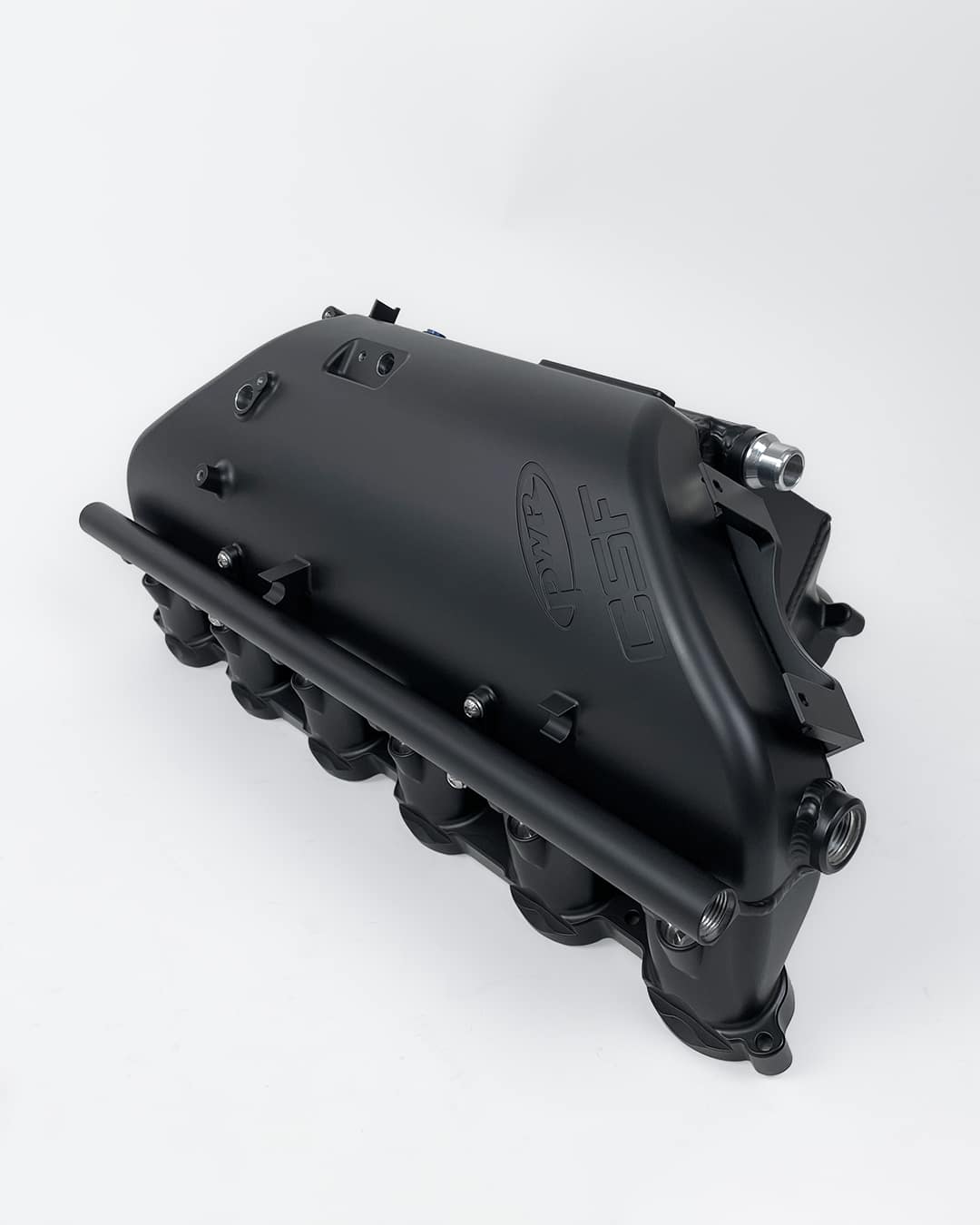
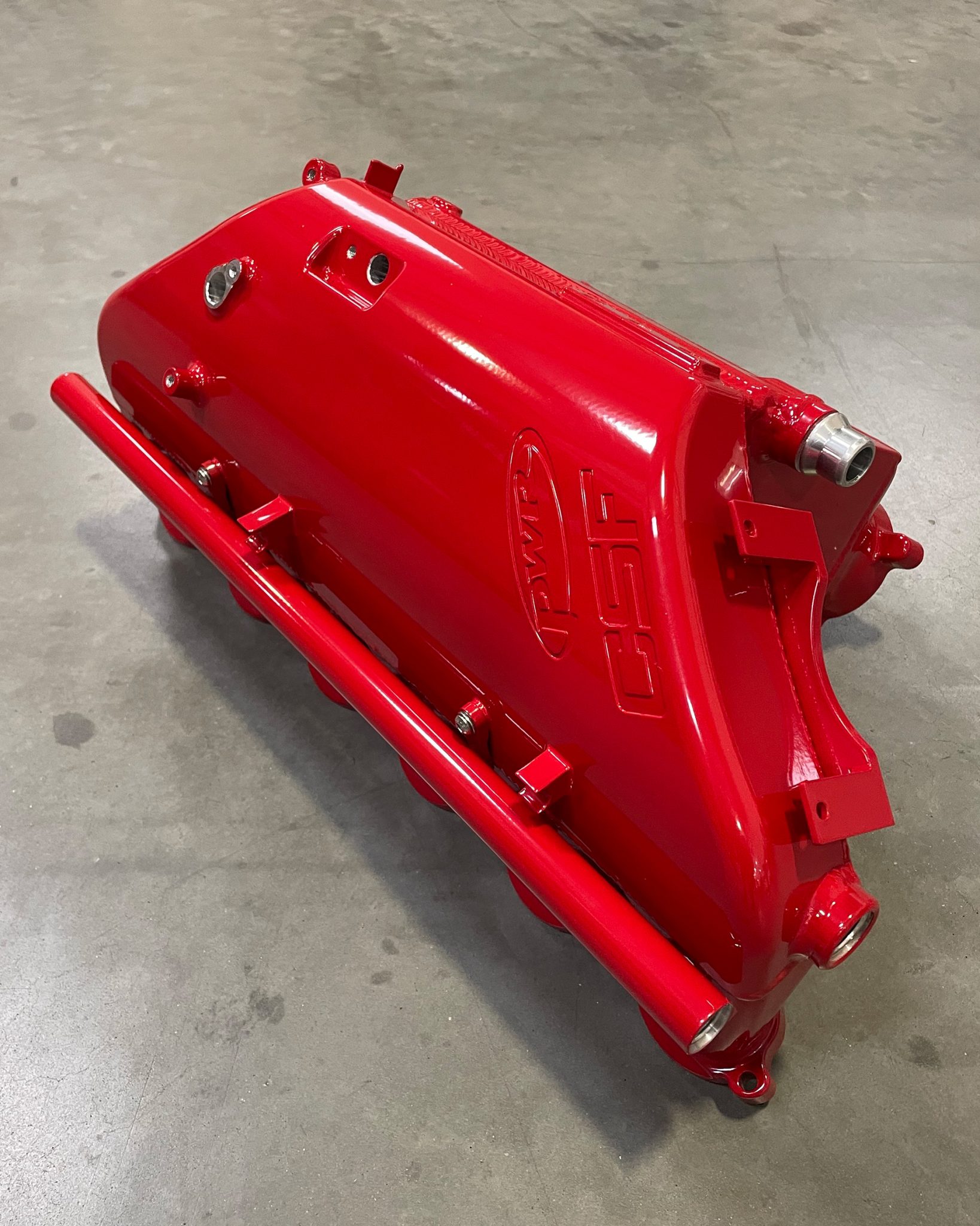
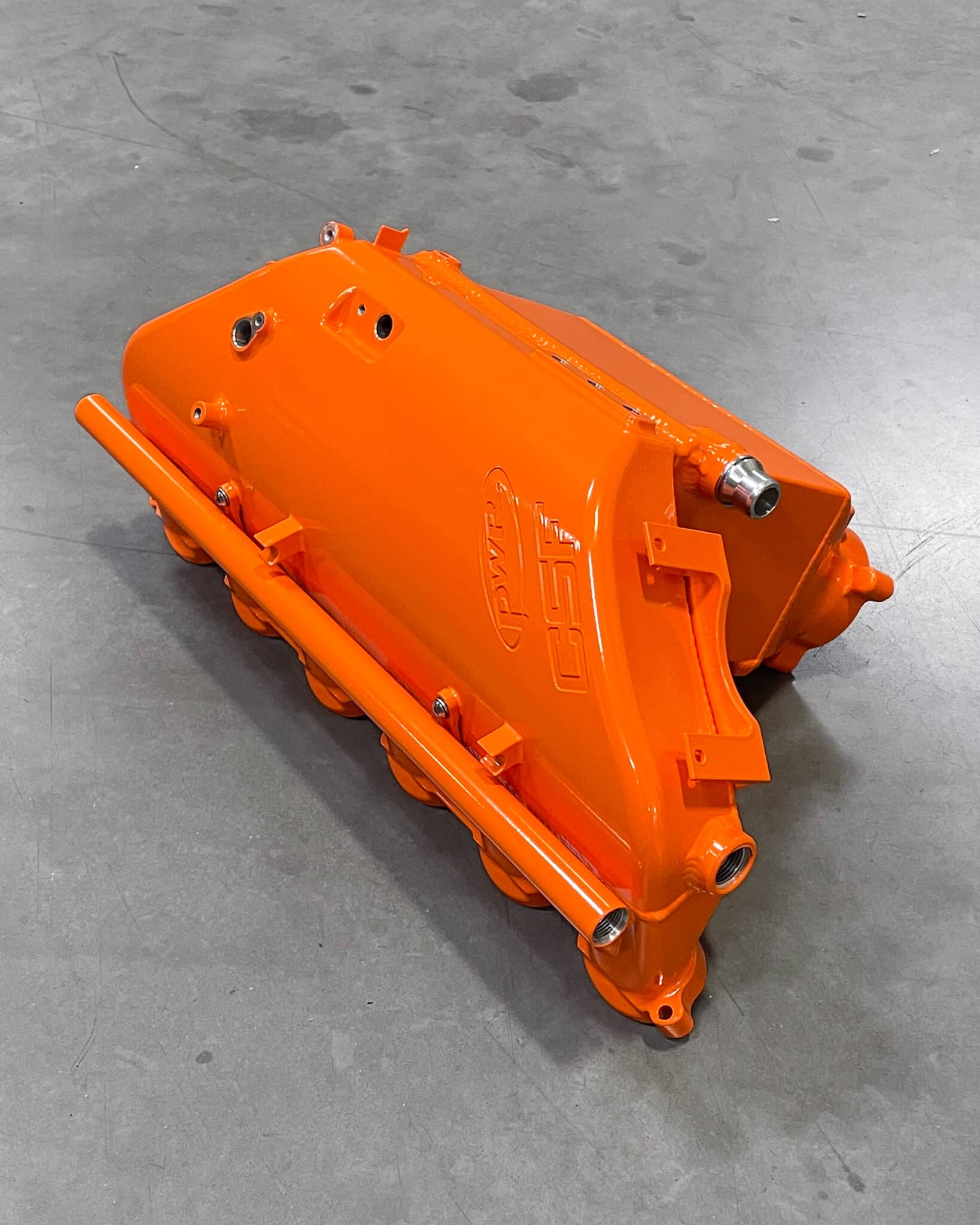
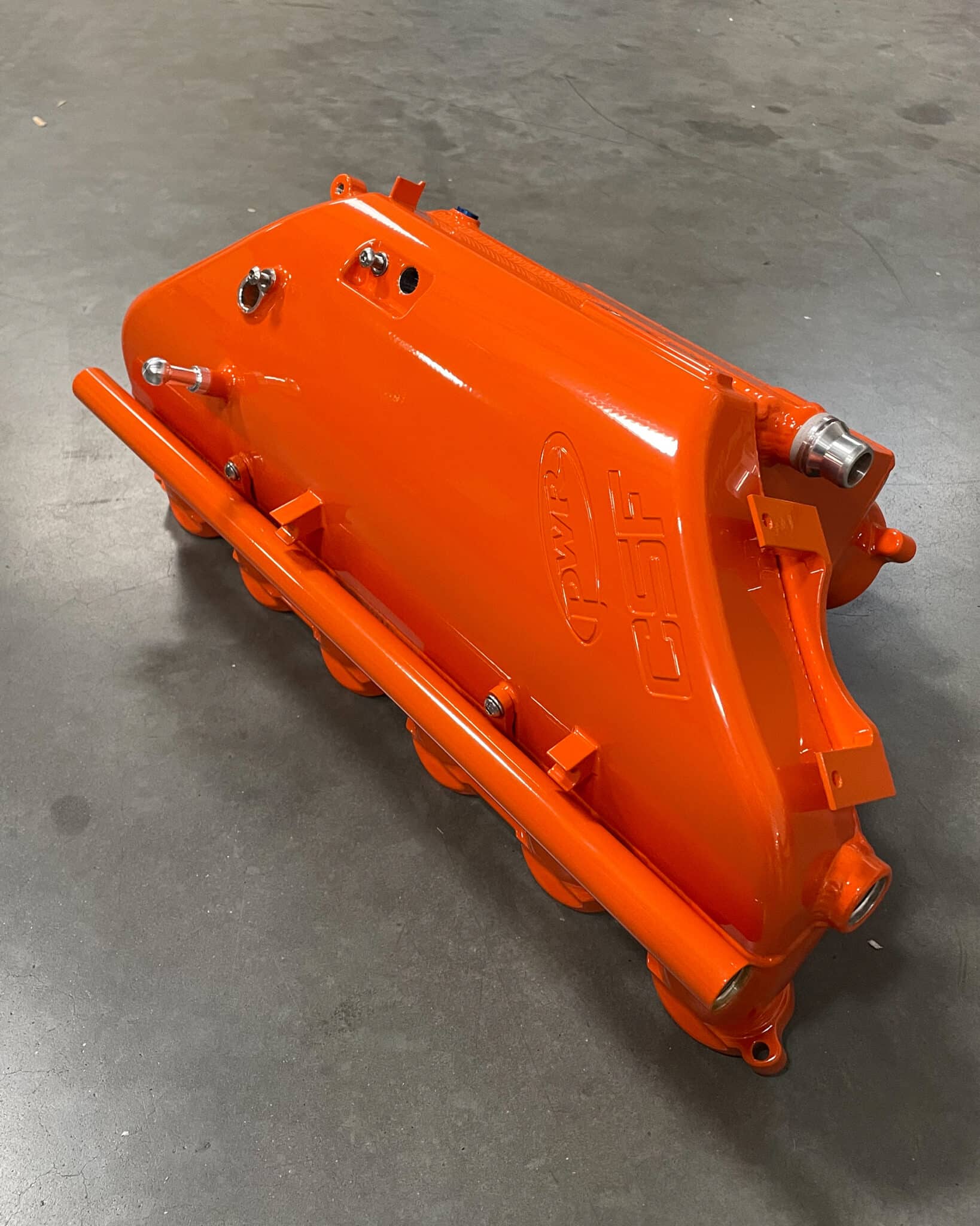
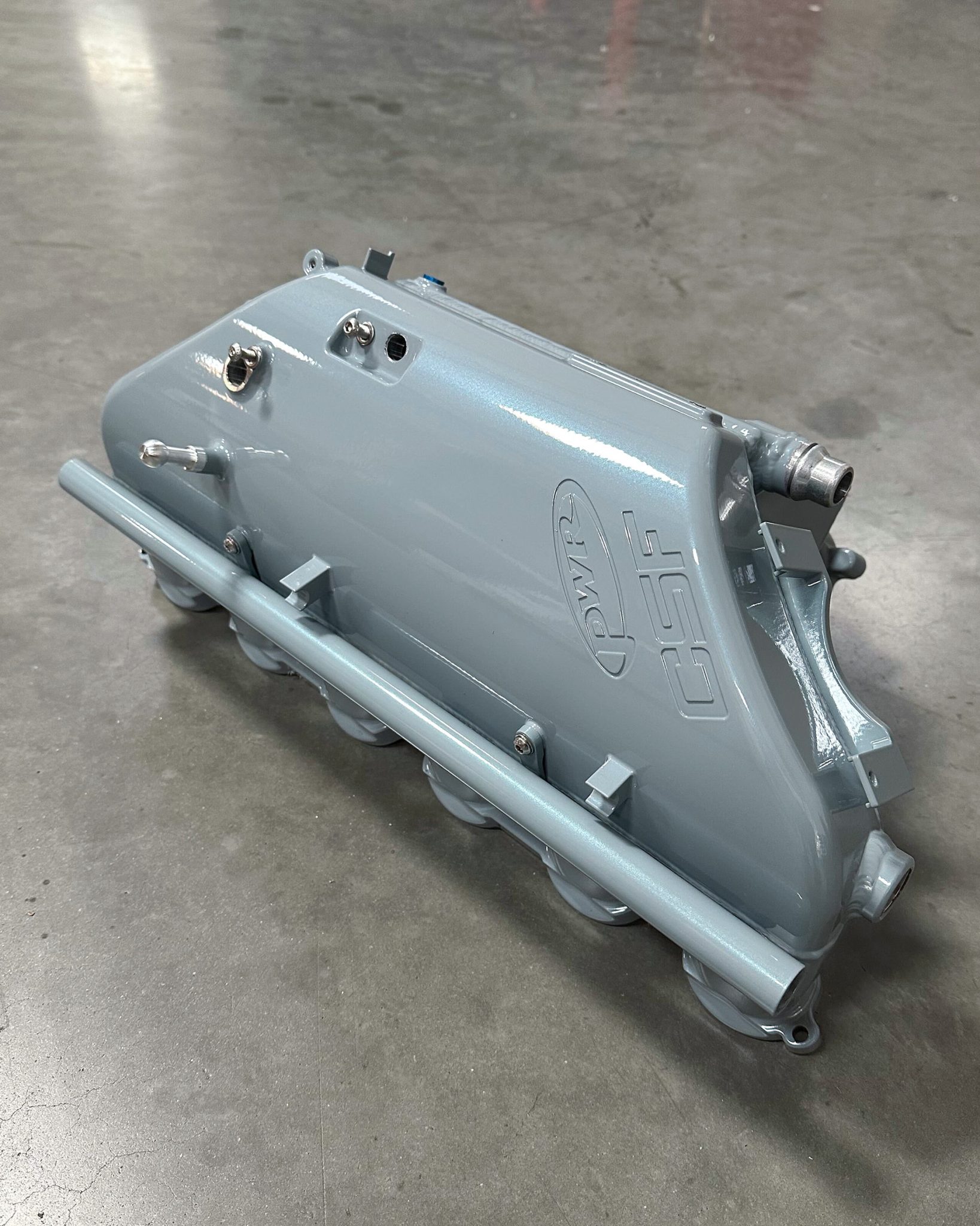
CSF’s most popular custom finish, Thermal Black Heat Dispersion Cerakote is now available as a standard finish option. This offers faster turn around time for orders and some dealers/distributors stocking this finish option.
*Exclusive Feature
Returns Policy
To RETURN any system, product or merchandise you must contact us first for a Return Authorization (RA) Number. Special order and custom made systems, apparel, limited production parts, Carbon Fiber Parts, and other certain merchandise are NOT returnable. ALL SALES ARE FINAL. To return a Grid Racing Parts product an RA number must be requested and if granted the item(S) must be in original Grid Racing Parts sealed packaging. A copy of the original invoice and a brief explanation must accompany all returned items. You must follow our instructions for returning items carefully, or Grid Racing Parts reserves the right to charge a 30% restocking fee on any OPENED box or repackaged products. Customers are responsible for return shipping charges. If an order was shipped with a promotional “Free Shipping”, and the order is returned, we exclusively reserve the right to charge the customer or distributor for the cost of that original shipping and handling. If a Grid Racing Parts Performance package is ordered, and an individual component of that package is returned, Grid Racing Parts reserves the right to charge back the performance package discount along with any additionally offered discounts. Return shipped items DAMAGED in transit will RESULT in additional charges up to and including rejection of the competent. It is the customer’s responsibility to ship safely and properly. No returns accepted after 30 days from the invoice date. No credits will be given after 30 days from the invoice date.
To qualify for return, the product must be unused and remain in the original packaging, as well as match the current design and packaging for the product at the time of return. Sounds is subjective and therefore does not qualify for a return of a used product. See Sound Solution Guarantee to see if your product is covered.
Periodically mistakes are made when ordering, or a wrong part is shipped, and you may wish to return an item. We will do everything reasonable to satisfy you. Please contact Grid Racing Parts immediately via email at service@GridRacingParts.com to discuss the circumstances before returning any products. Anything returned without prior authorization from Grid Racing Parts will be refused. All returns must be sent back fully prepaid. Our customer service department (service@gridracingparts.com) will issue a Return Authorization Number, which must accompany any return. A copy of the original invoice and a brief explanation must accompany all returned items. No returns accepted after 30 days from the invoice date. No credits given after 30 days.
Shipping
Grid Racing Parts Motorsport cannot be held liable for refusal of, delay of, loss of, theft or damage to a shipment of any item. The customer agrees to indemnify Grid Racing Parts for all costs, fees and expenses Grid Racing Parts incurs as a result of any violation of any local, state, federal, national or international laws or regulations. Customer agrees to take responsibility for lost packages that were not independently insured or sent without requiring signature. The customer understands they will be liable in the event of additional fees, tariffs, or legal issues such as border seizure. Customer accepts these risks and agrees to release Grid Racing Parts of all liability.